quasiturbine.promci.qc.ca
Page replaced by: EProductQT75SCAcademic.htm
* * * * *
QUASITURBINE EDUCATIONAL
QT75SC
FRANÇAIS -
ENGLISH
Occasionally available on www.ebay.com - Search
for "Quasiturbine"
Price : 1890,00 $US in America or 1890,00 Euro
elsewhere (equivalent of 40 students at
50
$-euro each! )
M
Attach an accepted copy of the present pages with your purchase order.
(For completely assembled engine, see
http://quasiturbine.promci.qc.ca/QTdesireacheter.html)
LET THEM INVOLVE IN THE
"QUASITURBINE STUDENT INTERNATIONAL CHALLENGE"
IT IS FUN AND HIGHLY EDUCATIONAL !
SET OF BASIC PARTS (PARTIAL KIT)
FOR CONSTRUCTION
OF A
DEMONSTRATION PROTOTYPE OF A
QUASITURBINE PNEUMATIC ENGINE
(Air motor)
Quasiturbine Académique Inc. offers a set of educational basic parts (partial
kit),
from parts
similar (but not as powerful) as those used in commercial Quasiturbine QT75SC-Pneumatic models.
|
It is the buyer and/or operator
responsibility |
The Quasiturbine technology is under development
and the prototypes are still experimental.
These prototypes only have an academic-educational vocation,
and consequently do not seek to meet high standard of performance or durability.
Although functional, these sets of basic parts are not intended for commercial practices.
They are not intended to produce useful power, nor for
steam or hydraulic use.
Once supplemented and assembled, these pneumatic-academic prototypes of
demonstration turn under the effect
of compressed air or nitrogen at a pressure as low as 0,3
bar (5 psi)
and must
not exceed 1500 RPM and/or 2 bars (30 psi) at the pressure gauge
(About 1 HP flow-in).
However, don't anticipate a perpetual loop motor-compressor-motor,
nor to extract 1 HP out of a 1 HP compressor, this motor will not do this
kind of magic !
To make a success of this project, it is essential to have good knowledge in
mechanics.
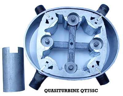
External engine size is about 19.8 cm (7 7/8 inches) in diameter
by about 6.4 cm (2 1/2 inches) thickness.
Well constructed and assembled, well lubricated and operated within the limits,
these prototypes can generally totalized several hundreds of hours
without significant breakdown and/or weariness.
BY THE PROJECT (not necessarily provided)
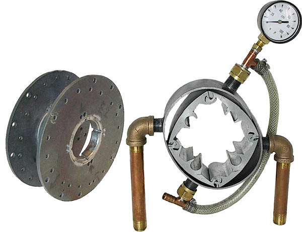
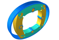
(The QT75SC is similar to the QT50SC shown in this picture)
Includes a simplified differential and
a central shaft.
For educational purpose, it is suggested to observe the rotor turning by the
openings on the axis of the side covers.
These prototypes do not
use lateral seals,
sealing being only assured by tight side tolerance with the assembly and by
the lubricant used.
* * *
WHAT IS INCLUDED
IN THE SET OF PARTS OFFERED (partial kit)
(The QT75SC is similar to the QT50SC shown in this picture)
1) A set of 4 pivoting blades slightly oversize in thickness.
2) A steel stator slightly oversize in thickness, whose interior surface is
already rectified and polished,
and including 4 radial windows (two intakes and two exits,
standard NPT 1/2").
3) A set of 4 slightly oversize contour seals and their associated springs
(seals which have to be slightly rectified to accommodate the contour).
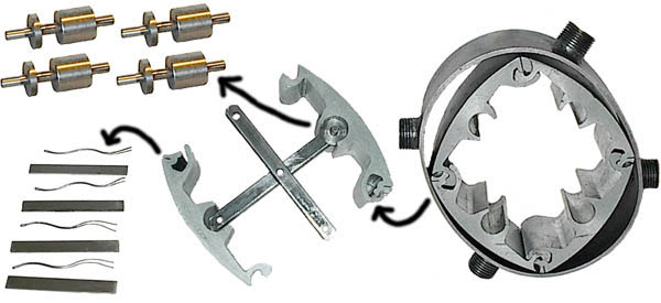
4) 4 cylindrical supports and 4 axes for the pivoting blades.
5) Two central cross arms (no suitable as power takeoff).
6) A suggested drawing to help making the lateral side covers.
7) Includes a simplified differential and a central
shaft.
7) A Guide of indicative instructions for assembly and construction.
* * *
IN THE SET OF PARTS OFFERED
(The QT75SC is similar to the QT50SC shown in this picture)
1) Two lateral circular side
covers including the
tracks for the rollers supporting the pivoting blades.
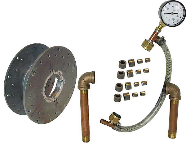
2) 8 central rollers supporting the pivoting blades and their needle bearings.
3) The connecting holding bolts.
4) Ports of admission and exhaust compatible with NPT 1/2" standard .
5) Final correction, settings with the dimension, selection of the tolerances,
polishing, adjustments, assembly...
6) The foot for anchoring the engine to a table (essential to build it).
7) The tools, abrasive pastes and the facultative antifriction pastes.
8) The pin-hole pressure gauge, the tachometer and compressed air
or nitrogen (neither
the compressor, the bottle, nor the regulator).
9) The static or dynamic
rotor balancing has not been verified.
10 -
Includes a simplified differential and a central
shaft.
* * *
- Familiarize yourself well beforehand with the Quasiturbine
technology (see the associated site
- Always make it turns gradually (without abrupt acceleration).
- In phase of running in, reposition the rotor before each starting
by making turn the rotor by the central shaft.
- Always ensure that the rotor is adequately lubricated (pneumatic tool oil).
- Ensure that the hoses and fasteners (particularly the flexible) are of
quality and well anchored.
- Use a good pressure regulator to limit the maximum pressure and place a
pressure gauge close to the engine intake.
- It is recommended not to exceed 1500 RPM and/or 2 bars (30 psi) at the pressure gauge
(About 3 HP flow-in).
- The use of a tachometer (with magnetic pick up, like the one used on bicycle
?) is also recommended.
- Once in use, the engine will progressively break-in and rotate better and
better,
the fact to later dismantle periodically the engine may require a new
running-in period every time...
- Never exceed the recommended limits.
REMARK ON PNEUMATIC SYSTEM EFFICIENCY
An high efficiency pneumatic motor does not guaranty the high
efficiency of the entire pneumatic system.
All gas heat up during compression and cool down during relaxation.
The cooling effect must not be under-estimate. As an example, a typical 200 bar
(atm.) cylinder
empty adiabatically (without thermalization to ambient temperature) gives at the
end an air so cold
that its volume is then a 1/4 of that of the air once back to the ambient
temperature (isothermal relaxation).
In those temperature conditions at the entrance of a pneumatic motor, the
efficiency is catastrophically low
and the lubricant solidified, increasing considerably the internal engine
friction...
Generally, the reversibility of the compression - relaxation cycle reduces with
an increase in pressure,
which favours for high efficiency consideration the use of the lowest design
pressure possible.
The measurement of the exhaust temperature gives generally a good indication of
the efficiency,
since the minimum of energy lost into the environment correspond to
an exhaust temperature equal (neither inferior, nor superior) to the ambient
temperature.
This condition can be achieve by a slight heating (solar) of the gas before its
entry into the pneumatic motor.
Since the Quasiturbine rotates from pressure as low as 1/10 of atmosphere (bar)
(one psi !),
one understand why the Quasiturbine is so well adapted to high efficiency
system...
- These prototypes must be supplemented, assembled and
operated under the constant supervision of qualified adults.
- Anchor the prototypes well on a table before each start-up.
- Never exceed the limits and suggested conditions of operation.
- Wearing safety glasses, mask and fastener hair is recommended.
- The demonstration room must be well ventilated.
- Check the tightening of the bolts and adapters. Be wary of the rupture
or the decoupling of any of the flexible hoses.
- Have a distant valve allowing to cut the air flow (nitrogen) as
needed.
- Particularly during grinding under compressed air, it can happen that the
rotor be at a dead point,
and refuses to turn when the pressure is applied.
This situation is unstable and call for urgent pressure release.
Then and in absence of pressure, slightly turn the rotor with the central
shaft and pressurize
it again...
- During the demonstration, nothing should approach the central zone of the rotor
and makes the observations at a distance of 50 cm (20 po.) or more.
-
Always remain vigilant!
- Includes a simplified differential and a central
shaft.
SALE DETAILS
GENERALITIES
- Sale and operation is restricted to adults only.
- Sale priority goes to schools, colleges and universities.
- Use for academic demonstration only (commercial modification is
not suitable, nor recommanded).
- Pneumatic air-nitrogen prototype only (less than 2 bar - 30 psi),
no steam conversion attempt must be made (could be very dangerous).
- Prototypes intended for demonstration of short durations.
- Additional parts of replacement can generally be ordered by those having acquired the kit.
- The Brief Instructions
Guide suggests data and methods only as
indication,
and it is up to the purchaser to make sure that he-she understands well
the steps and the details of his project.
- To make a success of this project, it is essential to have good knowledge in
mechanics,
in machining technique and assembly.
CONDITIONS
- The Purchasers release Quasiturbine Académique Inc. of all responsibilities
relative with the use.
- Sold without specification, nor guaranteed of performance or durability
(variable according to the quality of the assembly).
- Guaranteed of the seller (Quasiturbine Académique Inc.) is limited to the
replacement of the parts with manufacture defect.
- The prototype can not be used to make research on the Quasiturbine
technology,
neither to make reverse engineering, or to make copies.
- The purchasers must have read the present page as part of the purchase order
and invoice,
and
declare themselves satisfied with it.
- Sales are assumed done in Montréal, Québec Canada.
- The present document and conditions will be transferred
to the chain of future owners of this prototype.
- If there is intellectual propriety risk, the seller can simply refund and not
deliver.
PRICE AND SHIPPING
- The set of basic parts (partial kit) is
sold on
at a starting price depending of the monetary zone of 1890,00 $US or 1890,00 Euro (equivalent of 40 students at
50
$-euro each! )
-
Attach an accepted copy of the present pages with your purchase order.
- The price includes the applicable local sale taxes if required, but not the shipping costs.
- Approximate Weight of the parcel is 5 kg (12 lb).
- The insurances (mandatory) and customs fees are the responsibility for
the purchaser.
- As possible, shipping will be made in the 3 weeks following the
reception of the payment,
or according to the production capability of the moment (to be notified when ordering).
* * * * *
SET OF BASIC PARTS (PARTIAL KIT)
FOR CONSTRUCTION
OF A DEMONSTRATION PROTOTYPE OF A
PNEUMATIC QUASITURBINE ENGINE QT75SC
|
It is the buyer and/or operator
responsibility |
Notice - This document is written
to be used by a mechanic experienced with the said techniques.
If you do not understand well some sections, you are invited to consult a
professional mechanics.
Follow attentively the instructions and read again at each later dismantlement and re-assembly.
I - Attention: The rotor is a deformable assembly articulated
in square and lozenge.
OF THE ROTOR PASS ITS LIMIT
nor strikes the pivoting blades to articulate the rotor
(what could distort the pivots and the grooves of
the contours seal).
II - Attention: Abrasive
grinding paste, only if necessary to use,
ALWAYS USE IT IN "VERY SMALL QUANTITY"
(hardly visible quantity) abundantly diluted in a lubricant.
Avoid the formation of a film of paste on surface to be polished.
NEVER ADD GRINDING PASTE TO THE ASSEMBLED ENGINE
Once finished, always clean well with solvent all the parts and the tools
contaminated with the paste.
III - Attention: If the rotor does not turn freely
by
hand,
DISMOUNT IMMEDIATELY
otherwise irrevocable grooves can occur on the interior face of the stator or
elsewhere.
IV - Attention: Foreign bodies
OF FOREIGN BODIES IN THE QUASITURBINE
A way is to use screen and make sure the intake
line goes from bottom up.
V - Attention: These prototypes must be supplemented,
assembled and be operated under the constant supervision of qualified adults.
OTHER SAFETY MEASURES
- These prototypes must be supplemented, assembled and
operated under the constant supervision of qualified adults.
- Anchor the prototypes well on a table before each start-up.
- Never exceed the specifications and suggested conditions of operation.
- Wearing safety glasses, mask and fastener hair is recommended.
- The demonstration room must be well ventilated.
- Check the tightening of the bolts and adapters. Be wary of the rupture
or the decoupling of any of the flexible hoses.
- Have a distant valve allowing to cut the air flow (nitrogen) as
needed.
- Particularly during grinding under compressed air, it can happen that the
rotor be at a dead point,
and refuses to turn when the pressure is applied.
This situation is unstable and call for urgent pressure release.
Then and in absence of pressure, slightly turn the rotor by the shaft and pressurize
it again...
- During the demonstration, nothing should approach the central zone of the rotor
and makes the observations at a distance of 50 cm (20 po.) or more.
-
Always remain vigilant!
- Includes a simplified differential and a central shaft.
Parts provided
VI - The the rotor and the stator
thickness fit.
These parts are delivered slightly over-dimensioned.
Do not use electric tools or motorized grinding stones.
It is recommended to make this dimension setting by hand
with the
already encased pivoting blades ones in the others (Always match the
pivot numbers - Facing the one or two dots)
by using sandpaper posed on a plane surface, the rotor being then caped also
by a plane
object.
The rotor must have good parallelism in its two extreme lozenge positions. It is
then recommended to deform it while lapping.
Control the rotor thickness for different geometries by squeezing it in-between
two flat surfaces.
Attention not to déburer (to round the edge)
at the stator interior, which
would increases the leaks.
For the compressed air, it is suggested a minimal difference in
thickness of 0,002"(maximum 0,005")
between the rotor and the stator, and check free rotation once assembled
(the numbered surface of the rotor should be on the same side as the arrow
grooved in the stator),
like while moving under pneumatic in order to taking into account a possible heating
dilation of the pivots.
Multiple tests will guide you towards the optimum value.
Multiple resumptions of the dimension settings of the stator
and rotor are generally possible.
QT75SC Pneumatic (the simplified differential and its shaft actually replace the
central cross).
(Rotor average diam. 6 in. by 2 in. thickness)
VII - The interior surface of the stator.
This surface was already brought to the dimension and reasonably polished.
It is necessary to avoid deteriorating this critical surface, because it would
be so to speak be non reparable. ..
This surface required a complex polishing equipment - Do not attempt to re-grind
this surface.
VIII - The fitting of
the grooves and the contour
seal .
Each pivoting blade comprises a contour
seal
which must move freely in his
groove. It is suggested not to sandpaper
or grind the
interior of this grooves,
but rather to notch it using a blade of wished width,
typically 3,18 mm (0,125") with square and sharp
ends.
The back and forth of the end of this blade should be enough to form the
grooves.
The set of parts includes slightly
oversize seals,
the length must be brought back to about 0,003"
shorter than the thickness of the stator.
Once at the right dimension, the contour seal inox sleeve (when present)
must be slightly squeezed
with its contour seal inside to insure the best movement with minimum of
friction.
The edge of the seal in contact with the stator
contour must be round on a stone to avoid gripping,
and the opposite edge must be grinded down in order to leave a reasonable play
in the rotor.
Undulated springs to place behind the contours
seals are provided
but the tips must be smooth out not to grip into the seal, neither scratch the
lateral covers.
(Notice that rotation in excess of 1500 RPM may provoke early fracture of the
springs).
Always check the unrestricted passage of these
seals during the
rotation of the rotor.
IX - Supporting blade rollers axis and the
simplified differential. These parts are provided
and already assembled in the pivoting blades and the rotor
at delivery. If need,
it is possible to dismount them and put them back up again.
They do not require any intervention other than checking the length to
ensure a sufficient gap in the between lateral side covers.
Lubricate well all the parts, and periodically the flat part on the shaft.
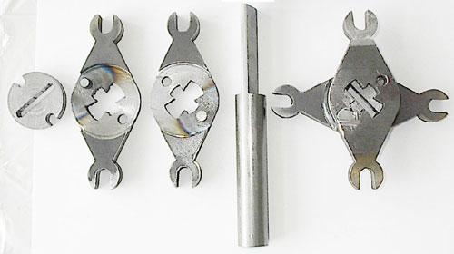
Simplified differential : The components on the left, the shaft at the center,
and a view once the left parts are assembled on the right.
Parts not provided
X - Central
supporting rollers and bearings of the
pivoting blades. These parts are not provided,
because they must be made according to
the residual tolerances measured
between the rollers on the rotor
and the supporting track in the lateral side covers. It is strongly suggested
to mount these rollers on bearing (e.g. Torington B56),
and their external diameter will be close to 0,780"
in order to allow a free movement of the
lateral side cover tracks in and out of
the rotor.
Polish the sides of the rollers on bearing and make an initial generous
lubrication
to avoid wear against lateral sides covers and the rollers supporting shaft
support .
Important : It is not acceptable
to force the side cover tracks into the rotor
and if that is the case, it is necessary to under-size the
external diameter
of the rollers supporting the pivoting blades.
If needed, the central 1/2" diam. hole of the blade supporting wheel-bearing
must be slightly enlarge to make sure the bearing casing (type Torington #B56)
moves freely axially in this hole.
Attention : Do not attempt to rotate the rotor without the 8 wheel-bearing
well in place on the supporting tracks.
These wheel-bearing are as important as the bearings in the pistons engine,
and an attempt to rotate without them shorten the engine live time to a few
minutes !
XI - The lateral side covers.
These lateral side covers are not
provided because they can take several external forms
(square, rectangular, circular. ..) to suit the local needs. They do not present however an particular
difficulty of realization.
Although the commercial versions require a quality steel, the
demonstration versions are well
served with ordinary steel.
Aluminium is not suitable unless a flat steel sleeve is added and an steal ring
insert is used for rollers tracks.
The lateral side covers can be cut in the mass in
only one part, or be made of two
pieces welded together.
The following suggestive drawing present a possible distribution of the positioning of
the bolts. Notice the protuberant track.
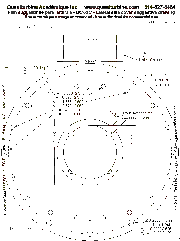
It is important to
precisely position the holes of the bolts, because
their location are also used for centring the stator.
The central circle on the lateral side cover drawing is the maximum diam.
suggested for that opening.
A smaller diameter hole would improve the cover rigidity
(as for example a 1" diam. only to accept a needle bearing type Torington
#B128).
One of the lateral covers may have 10-24 threaded stator holes to conveniently
avoid using nuts !
XII - Connecting holding bolts. These bolts are not
provided.
It is suggested to use 3/16" (10-24)
bolts of sufficient length, and
quality nuts.
The cheap steel bolts elongate with time and are not adequate. Use only forged
steel bolts grade 9 or higher (Allen head).
Suggested phases of assembly
XIII - The centring of the stator. This centring
is important, and it is made in reference to the connecting holding bolts.
Before closing the cover, it is recommended to extend the rotor fully in the
diamond configuration,
and to make sure all four contour seals are equally extended.
Angularly, make sure that the stator is in the
wanted position in relation to the
lateral side covers orientation.
Ensure that the bolts are
straight, or substitute some by rigid
rods at the
lateral side covers assembly time.
Use external appropriate spacers at top and bottom,
and on the left and the right, in order to hold the stator correctly.
Tighten the bolts well, because they must immobilize the stator in place.
The standard academic stator has no privileged direction of rotation, which is
not the case for the
rotor direction of rotation : In between two successive contour seals,
localized the jointure interstice,
which should be head of the rotation when the rotor rotates.
Note : Due to the in-out port symmetry of the academic stator,
the air motor can be assemble without at that stage considering the rotor
direction of rotation,
which direction being later defined by examining the jointure interstice
through one of the ports,
which ports will then be assign as in or out according to the rotor
preferential direction of rotation.
In this case however, the engine base support may not be on the desired side
for a given direction of rotation.
XIV - Assemble and test one step at the time.
Place the rotor without its seals and neither its rollers in the engine casing
and tide all the bolts
(important to avoid the deformation of the lateral side covers). Ensure that the rotor move freely.
Put it apart, add the contour seals and bolt it again to check the free rotor
movement in between the two lateral side covers.
Keep doing that way for each assembly step.
This way to do is crucial not to damage the components of the engine.
A resumption of the thickness of the rotor and stator are generally
possible,
but it should then be made sure that the 4 axes, 4 supports and 8 rollers of
central pivoting blades
do not exceed the total thickness of the
stator.
Check the lateral side covers with a ruler for deformation.
Excessive torque on the contour bolts or the insufficient lateral side covers
rigidity may lead to spherical cap deformations.
and make impossible the proximity leakproof rotor condition with the lateral
side covers.
If needed place 4 cylindrical spacers, diam. 1/4" and having the same length as
the stator thickness,
near the engine attachment holes on the external perimeter. Control again the
external planitude.
XV - Use of anti-grip past : This paste is
not essential, neither recommended,
but it can facilitate the start-up by decreasing the risk
of damaging the parts,
particularly on the pivoting blades, the
grooves and contour seals,
like on the interior surface of the stator when use for the
first time.
Others suggestions
XVI - A hand key tool to reposition the rotor by hand.
For checking the assembly
and before each start up by compressed air, it may be
useful turn the rotor by hand.
For that, it is recommended to used a hand key
tool fitting on the shaft.
Before concluding that the engine is difficult to turn, it is recommended to
move the hand key tool alternatively in both directions.
The central simplified differential has a slot
to insert the flat part of the shaft of 3/4" diam. (thickness 3/16").
For a better holding and self centering, a different shaft could have its flat
section extended
such as to enter also in the opposed side cover bearing, and even further
extend outside the engine where it could be lock-in.
The simplified differential efficiently smooth out the engine torque but is not
as robust as an industrial units.
Attention : Be carefull to always remove the hand key before
running the engine !
XVII - A foot for
engine support. The engine
can produce violent kickback,
and as it has a substantial weight, it is imperative to immobilize it well
before each use.
It is thus essential to build a solid and adequate holding support.
Take care of the engine attachment method in all circumstances :
Important : Always attach the engine by only one of the lateral side covers
(the one on the power takeoff side)
using short bolts in peripheral holes,
in order not to add undesirable pressure in between the 2 side covers, which
could deform the engine casing.
XVIII - Periodic lubrication. During the
first 2 braking-in running hours,
periodically add oil in the feeding air line to help exiting the braking-in
particles.
Later, use moderate oil quantity and no more than necessary to wet the chamber
walls.
Furthermore, since the rotor lateral leakproof is only assumed by
the lateral side covers proximity,
a generous periodic lubrication help to complete the leakproof.
This engine is not
particularly demanding on lubrication,
but the materials chosen for these prototypes require nevertheless a periodic
lubrication.
Every hour of operation, add
some pneumatic tool oil drops in the
intake manifold
(motor oil emulsions, oxides and crystallizes under adiabatic cooling, so it
is not recommended).
Do not allow excessive oil or liquid accumulation in the central engine
area
to avoid a blade fatigue
by hydraulic lock of the micro pivots cavities.
Periodically, dip the flat section of the shaft in oil (use air tools
oil only)
to lubricate the central power grip zone.
XIX - The operating temperature. Air
expansion produces a powerful cooling.
These prototypes
are intended for demonstrations of short durations
of 30 minutes or less. If the
prototype must go for uninterrupted longer periods,
monitor the temperature of the
lateral side covers and stop at once
if it
does increase even slightly.
This prototypes has no dilatation provision for use with steam - Do not try
hot.
XX - The static or dynamic
rotor balancing has not been verified
and is generally not required for demonstration.
Everyone is free to improve the balancing at will if desired.
Version subject to changes without notice - December 17, 2004
******************************
Instruction
for theTo :
Quasiturbine Tronçonneuses Inc.
Casier 2804 - 3535 Papineau
Montréal Québec H2K4J9
514-527-8484 Fax: 514-527-9530
Associated website : quasiturbine.promci.qc.caA partial Kit of academic prototype
of the Quasiturbine model QT75-SC Pneumatic
(With a simplified central differential and shaft,
but not intended for useful energy production,
not to be integrated to a or several commercial products).
Only for academic purposes
and without guaranty of performance.
To be use only under competent supervision.Sale assumed done in Montréal, Québec Canada
Price including local sale taxes if applicable (1890,00 US $)The web page quasiturbine.promci.qc.ca/QTAcademiquePneumatiqueJeu.htm
is an integral part of the present purchase order
and constitute the terms and conditions assumed accepted by the buyer,
including the respect of the laws and the discharge of responsibility.__________________________________
Authorized Officer
******************************
| Retour au menu principal Quasiturbine / Return to Quasiturbine main menu |
Quasiturbine
Tronçonneuses Inc.
Casier 2804, 3535 Ave Papineau, Montréal Québec H2K 4J9 CANADA (514) 527-8484 Fax (514)
527-9530
http://quasiturbine.promci.qc.ca
quasiturbine@promci.qc.ca