|
|
Many new engine concepts are just
piston equivalent engines.
An equivalent engine is fine, but not enough to justify a paradigm shift.
The Quasiturbine has superior characteristics that no other engine has yet!
Theory - Quasiturbine Specifics
Why Is QT Exceptional?
This is probably the most intriguing page of this website, the most
unpleasant to read, the most hermetical, but the most promising of all. The Quasiturbine is universal in relation to
energy sources:
Liquid and gaseous fuel, hydrogen, steam, pneumatic, hydraulic... and offers
un-equal versatility.
|
Typical comparison:
Engine displacement versus the Total engine volume
4 strokes engine type
Unit displacement
Engine volume
Piston
1
15 to 20
Wankel
1
5 to 7
Quasiturbine
1
1.3 to 2
The Quasiturbine is a positive
displacement turbine
with a total displacement almost equal to the engine volume
(Imagine one day, a 3 liters car engine into a
3 liters volume!)
|
The Quasiturbine can be operated at
lower compression ratio, in standard Otto and Diesel cycle modes,
and the Quasiturbine AC (with carriages) has the fastest pressure ramp.
At low load factor, the intake depressurization of the Otto cycle
dissipates power from the engine since the throttle valve is almost closed and
the descending piston acts as a clogged vacuum pump against the atmospheric pressure,
which vacuum is subsequently partially destroyed
by fuel vaporization during the compression. Due to this effect, the
engine in Otto cycle opposes to all RPM revolution increase (well known as the
engine compression braking) and this intrinsic resistance to speed augmentation
is compensated by a constant and important fuel consumption. The detonation mode does not use any
throttle valve and accepts without constraint all available air at atmospheric
pressure (similarly as the Diesel, where the pressurization energy is restituted
at the time of relaxation). For this reason, the efficiency at low load factor
of the photo-detonation engine is twice that of the conventional Otto cycle, and
considering that the load factor of a car is in average of about 10 to 15%, this
is not a small difference (saving is still superior in the traffic jams...). The most important revolution of the
Quasiturbine comes from its characteristics permitting detonation which occurs at slightly higher
compression ratio than the
thermal ignition, designated in the US as "Homogeneous Charge Compression
Ignition" HCCI combustion, in Europe
as "Controlled Auto Ignition" CAI combustion, and in Japan as
"Active Thermo Atmosphere" ATA combustion. Even if the subject
passionates the researchers, the thermal and photonic ignition control in the piston is still
an unsolved problem, and possibly a dead-end that
the Quasiturbine does overcome!
But why does the Quasiturbine stand what the piston can not tolerate?
Simply because kinetics with vicinity of the "piston" TDC and the "QT-blade" are diametrically opposed,
simultaneously in volume and speed. In volume, because the piston passes at the
TDC at almost constant volume, whereas QT-blade passes the TDC with a
discontinuity in volume (slopes linear quickly ascending and
downward). In speed, because the
piston passes at the TDC with a discontinuous speed (deceleration, stop, and acceleration in opposite piston),
whereas the QT-blade passes the TDC at constant speed (with moreover a null radial component). Two mechanical considerations
rise directly from these physical characteristics.
-
Firstly, the piston is rising (kinetic ascending) when
the early photo-detonation comes to strike it (kinetic downward), and as
two objects moving in contrary direction hit violently, the piston
badly resists, whereas the QT-blade passes the TDC at
constant and null kinetic radial moment.
-
Second, the short pressure impulse of Quasiturbine
retains much less longer than the long sinusoidal impulse of the piston,
and consequently the QT-blade tires much less. Centrifugal force on the
blades of Quasiturbine also helps to contain high pressure.
For all those reasons, and considering what it is intended to achieve,
the Quasiturbine cannot be considered as a rotary piston engine.
Piston paradigms do not apply to the Quasiturbine!
Principle While most rotary engines use the principle of volume variation
between a curve and a moving cord, this new engine concept makes use of a
"four degrees of freedom X, Y, q, ø" rotor, trapped inside an internal
housing contour, and does not require a central shaft or support. The
Quasiturbine is a concept which improves the conventional engines in 2
ways : in reducing the dead time, and in making better time management in
the engine strokes. Keeping in mind that gas turbines have a compression
turbine and a power turbine, and that the Quasiturbine results from a
research initiated in 1993 aimed at unifying those two turbines into one
entity (blades of which work alternatively as a compression turbine and a
power turbine). Consequently, it should not be surprising that the
Quasiturbine shows similar characteristics with those of the conventional
turbine. On the other hand, engines that use crankshaft generate
sinusoidal volume impulses during which the piston stays a relatively long
time at the top while it decelerates and reverses direction, and stays
briefly at mid-course, which is contrary to the logic of a better engine
(Compression impulses should be as short as feasible, and the stay at
mid-courses the longest possible for a better mechanical energy
extraction). The Quasiturbine is also revolutionary because it generates
this new type of volume impulses differently from the crankshaft engine! (In
fact, the Quasiturbine asymmetry permits to devolve less time to the compression and exhaust strokes,
and more time and volume to the intake and expansion strokes). Furthermore, the
Quasiturbine brings the engine dead time to zero.
Consider the following figure where the Quasiturbine rotor confinement
"Saint-Hilaire skating rink profile" (From the name of the physicist who
first calculated this profile) is presented with the minimum and maximum
diameter circles and an elliptic reference profile.
Quasiturbine rotor confinement "Saint-Hilaire skating
rink profile"
This configuration displaces its entire volume every
revolution,
WHAT ABOUT A 3 LITERS DISPLACEMENT ENGINE
INTO A 3 LITERS ENGINE VOLUME!
Eccentricity can be still higher, but for current devices,
a less eccentric
Quasiturbine
is easier to built,
and well able to exceed piston engine performance.
High lozenge eccentricity (here 0,578 for the model QTSC - without carriage) may not be the most practical case
(corner angle goes from 90 - 30 to 90 + 30 degrees),
but it does emphasize the Saint-Hilaire skating
rink profile. Still higher eccentricity does make the straight top and bottom legs to become
convex, while still acceptable confinement profile.
The four pivoting blades rollers and the central annular supporting track are
also shown.
Careful observation near the TDC (top dead center) shows a triangular like
chamber.
Power on Demand
Multi-pistons engines have an advantage over a single larger piston in term of
torque continuity, vibrations and convenient packaging. In principle, there is no advantages
to stack many QT
on a same shaft, preferring a proper parameters selection at design.
However, because the Quasiturbine shaft is no-crank, multi Quasiturbines stack
can easily be done
with a simple ratchet coupling on a common shaft. Contrary to multi-pistons
crankshaft which can
not provide full power at both crank ends (because of crank torsion
deformation), this is not a
limitation to multi-QT stack.
Multi-QT stack would further allows power on demand by firering more than one QT
only when needed,
the other ones staying at rest, for the highest efficiency! (varying the number
of firing pistons
imposes to keep the dead pistons running free).
Quasiturbine Uniflow Characteristic
In most reciprocating piston engines, the steam reverses its
direction of flow at each stroke (counter-flow). By entering and exhausting the
cylinder by the same port, the cylinder valve and walls are cooled by the
passing exhaust steam, while the hotter incoming admission steam is wasting some
of its energy in restoring the temperature. Some energy is further lost in
reversing the motion momentum of the mass of steam within the piston. The aim of the piston uniflow is to
remedy this defect by providing an exhaust port at the end of the stroke, making
the steam flowing only in one direction, but has the inconvenience of
recompressing some residual cylinder steam. Quasiturbine is a uniflow engine,
with the further advantage of not recompressing any residual steam, resulting in
superior energy efficiency. Recompressing residual steam means some
reversibility losses, and the pressure increases makes a substantial restriction
to the initial steam flow into the chamber, not to ignore the truncated cycle
near bottom dead center - None of this with the Quasiturbine.
Specific Quasiturbine Elements
1 - Rapid transition at dead points: The "Saint-Hilaire skating rink
profile" (specially the model QT-AC with carriages)
allows the fastest possible transition around the top dead center (TDC). Considering that
the successive seals move in the inverse direction, all improvement to the rate of radial
variation is doubled in effect. In this case, a rotor move of no more than 10 degrees
brings the engine at 50% of its maximum torque.
2 - Torque continuity: Contrary to most rotating devices which are
progressive, meaning that the torque is nil at TDC and increases progressively until a
maximum is reached, the Quasiturbine "Saint-Hilaire skating rink profile" rapidly reaches the maximum diameter, and then follows it with accuracy on its
entire length. The continuous
combustion (flame transferred from one chamber to the other, not possible on the Wankel
engine) permits optimization of torque continuity. In assembling 2 units with a phase
difference of 45 degrees, one assures a positive torque for any angle of the engine shaft,
even at zero rpm. Lets recall that the Wankel fires 3 times per rotor (not
shaft) revolution (each space by a 30 degrees engine dead time), but since the
main shaft rotates 3 times faster than the rotor, it does fire only once per
shaft revolution, and has not this kind of continuity offered by the
Quasiturbine.
3 - Asymmetric cycles: The Quasiturbine furthermore benefits from the
fact that it looks much more symmetrical at first than it is. In fact, at top dead center
(TDC) the carrier seals are not 90 degrees apart, but are, however, in exact opposition.
The A and B seals are 77.7 degrees apart, while the B and C seals are angled 102.3
degrees. Consequently, due to the carrier rocking effect, the linear distances between
seals vary continuously, and a radial analysis does not permit a correct understanding at
full performance (The Wankel has its 3 successive seals at constant and equal
linear distance). A further asymmetry comes form the fact that the fixed intake
and exhaust ports can be located away from the middle cycle, giving more time
for intake and combustion gas expansion, and less time for compression and
exhaust.
4 - Comparison with the Wankel Engine -
See
quasiturbine.promci.qc.ca/ETheoryQTVersusWankel.htm
5 - High compression ratio: At the design parameter selection level, rotating
engines generally present a dilemma. If one wants to increase the compression
ratio, the intake volume has to decrease to an unacceptable level, thus imposing
large engine dimensions. The Quasiturbine does not present this dilemma, and
permits construction of a compact detonation or diesel engine. One understands
from #3 that the compression and exhaust is done on a 77.7 degrees range, while
the expansion (intake) occurs on a 102.3 degrees range. This asymmetry (impossible
in piston engine or conventional rotating device) brings the seals closer
together to give a higher compression ratio and allows the maximum extraction of
energy by an extended expansion cycle.
6 - Leakproof: The Quasiturbine does not have the critical leak proof
problem of the Wankel. The Wankel must make use of 3 seals at the triangle peaks
(Apex), which meets the engine profile with a variable angle on both sides of
the perpendicular (-60 degrees to +60 degrees). Since the Quasiturbine seals are
seated on rocking carriers, they are perfectly perpendicular to the engine
profile at all time. Furthermore, it should be noted that if the carrier wheels
are tight fit into the carrier, the wheels themselves are contributing to seal
the two consecutive chambers (the spring seal being complementary). Notice the
advanced mid-carrier "split seal" design suitable for very demanding situation
(like combustion engine) making use of a sloped groove and the internal pressure
to help maintaining itself in place at all time.
7 - Zero vibration on the shaft: The Quasiturbine is a true rotating
engine with a stationary gravity center during rotation devoid of any vibration on the
shaft (however like any other engine it is subject to unidirectional counter-torque
impulses). On the other hand, the Wankel is a "rotary piston" engine that is subject to a
constant circular vibration. It may be interesting to note that the Quasiturbine "Saint-Hilaire
skating rink confinement profile" is much more difficult to calculate
than the Wankel profile. Since there is no formula, a computer program needs to deal with
this difficulty.
8 - Fast acceleration: Due to the absence (and no need) of the flywheel and due to its low intrinsic inertia, the Quasiturbine is capable of fast
accelerations, including at low rpm. This quality makes it a "nervous" engine
and susceptible to please amateurs of sport engine devices. In comparison, the Wankel has
an important eccentric triangular mass which adds to the inertia and limits its
accelerations. Furthermore, the Quasiturbine can be started using compressed air from a
reservoir, pressure filled from the exhaust gases (A lever can be used to place the rotor
in the optimum initial position).
9 - Construction and reliability: The rotating engines are generally
comprised between a robust external profile and a central shaft seated on strong bearings
which are able to take the load on the shaft created by combustion pressure. For its part,
the Quasiturbine requires only a robust external profile on which the combustion pressure
load also applies; the central shaft is elective and only dedicated to torque transfer
when required. Furthermore, contrary to the Wankel, the Quasiturbine does not need any
synchronization gears (complicated and costly to built, and subject to lubrication and
weariness!), nor any spark plug synchronization. Conventional engines have achieved
excellent reliability considering their pumps, camshaft, rockers, push rod, springs,
electrical distribution... Having none of these devices, the Quasiturbine is then easier
to build, and eventually considerably more reliable (especially if the decision to use the
continuous combustion option is made). Having a low RPM, the Quasiturbine has a better
resistance to wear out and last longer.
10 - Energy savings: The Quasiturbine allows important energy savings
without having pretensions of a better thermodynamic performance than any other engine
(remember that 4-stroke pistons are propulsive only 19% of the time, and
dragging the rest 81% of the time). In fact, the ability of the Quasiturbine to generate a strong
and continuous torque at low rpm permits in numerous applications including
transportation, the suppression of the heavy and costly gearbox that consumes between 8
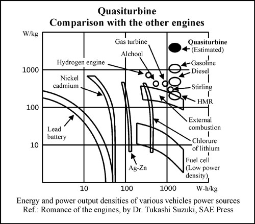
and 12 % of the energy. Furthermore, the best power to weight ratio of the Quasiturbine
(to which the flywheel suppression contributes) gives rise to lighter vehicles (also due
to the suppression of the gearbox) and fuel cost efficiency. The fact that the
Quasiturbine does not require energy consuming peripherals (pumps, camshafts, push rods,
valves...) also constitutes a gain at the level of energy efficiency. (See High-tech
for the detonation mode). Furthermore, the rapid expansion volume just after T.D.C. allows
to extract more energy from the initial hot gas with 3 advantages: thermodynamic
exhaust cool down, less heat transferred to the engine bloc, and less NOx
production. Energy efficiency is related to all the following :
- Thermodynamic (gain from early and late mechanical energy extraction)
- Thermal (smaller heat flux and cooler operation)
- Friction (the product friction X displacement is lower that for the piston)
- Peripheral accessories (gain because of no camshaft, valve, push rods ...)
- Peak power (only 20% higher that the mean power, compare to 7 times for piston)
- Shaft RPM harmonics (which are very low - no need of flywheel to average)
- Gear box saving (8 à 12 % energy saving by not using gearbox)
- Long life time (wear is measured in number of passages, low RPM means long life)
- Intake efficiency (piston has poor sine wave intake characteristics)
- On board application saving (lighter vehicles ... means saving over 10 years!)
- Fuel additives (Quasiturbine requires much lower octane level)
- Environment (fuel savings and much less NOx production)
- Vibration zero (source of $ billions of damages and corrosion acceleration)
- Cumbersome (4 times less than the piston engine)
- Weight reduction (5 times less than the piston)
Note on the Pressure-Volume diagram: The engines present cyclic
characteristics which are particularly well established by a close curve on a
pressure-volume diagram. In the case of the piston where the pushing surface is
strictly equal to the surface generating the volume, the surface enclosed in the
close pressure-volume diagram curve is then proportional to the work (energy)
done by the gas.
11 - Environment: It is well known that the 2 cycle engines are light and
nervous, but also very polluting. The reason for this pollution is due to the
fact that, in the 2-stroke engine, the exhaust gas are blown out of the engine by
the incoming intake mixture, and in order to have a maximum power, part of this
intake mixture passes directly to the exhaust manifold without having been
burnt. In the Quasiturbine engine, intake mixtures never come into contact and
neither are "pushing" the exhaust gases. Consequently, the Quasiturbine has
power characteristics of the 2 cycles engine, while meeting the excellent
exhaust combustion of the 4 cycles engine. For environmental reasons, we will
most likely stop using actual versions of the 2 cycles
(fuel injection being a possible improvement). The Quasiturbine engine will then
be one of the few alternatives to consider !
12 - Variety of fuels: In engine mode, the Quasiturbine is an excellent
pressured fluid energy converter (pneumatic motors, steam engines, zero leak
hydraulic engine for water fall, etc). Large units may be used to produce
electricity in coal or heavy oil thermal power plants, or to transform in
mechanical energy the residual steams of industrial processes. In addition to
the use of conventional liquid petroleum fuels, the Quasiturbine can in
principle make use of (if adapted) a wide variety of fuels from methanol to
diesel oils, including the kerosene, the natural gas and eventually the hydrogen
(See High-tech). About using computerized carbonation, one must realize that the
flow in the intake pipe is very continuous, and not shopped like in the piston
engine. In fact, the intake pipe load factor is expected to be 3 to 5 times
better, so that continuous fuel injection is appropriate without any
synchronization.
13 - Electrical integration: The Quasiturbine permits for the first
time a complete monolithic integration of the electric generator with a fuel engine (much
in demand for hybrid applications, and without vibration). Due to the fact that the center
of the Quasiturbine is free, the fixed electrical components can be simultaneously on the
central core, and on the peripheral stator. Only the intermediary zone is in rotation.
Reciprocally, if the electrical components make a motor, the Quasiturbine becomes an
integrated electrical pump-motor, or a bi-energy power plan.
14 - High-tech: Hydrogen is, without a doubt, the highest in high tech
fuels. However, high inflammability of hydrogen imposes a stratifiable intake chamber to
the engine distinct from that of the combustion chamber (which disqualifies the piston
engine) . The Wankel engine success for direct hydrogen combustion comes for its
intake and combustion stratification, which results mainly from early intake (like
Quasiturbine) and its excessive volume during expansion (with an efficiency lost). The
Quasiturbine engine offers the same hydrogen advantage, without the lost of efficiency and
hydrogen oil degradation (oil free). The Quasiturbine meets the
fundamental criteria imposed by the "hydrogen" engine of the future (cold
intake area, stratified intake, reduced confinement time, low sensitivity to detonation,
less pollutant, robust and energy efficient), and even surpasses the Wankel in
this respect, since the intakes are separated by 3 strokes instead of two.
15 - Oil free engine, compressor and pump: In the
Wankel engine, the oil pan is also mandatory for shaft, bearings, gears lubrication and
thermalization. In the Quasiturbine, oil is not a cooling agent, and is only required at
seals friction interface. Use of ceramic or high tech seals can make the Quasiturbine an
oil free engine (Thermalization being done by the contact of the carrier wheels).
Furthermore, since hydrogen degrades all oil, lubrication free must be developed for
hydrogen engine any way. For units built with conventional materials, a lubricant can be
added to the fuel or the vapor. Notice that units with exhaust in the lateral covers (and
not radially) are true centrifuge oil traps, and the needs of lubricant are consequently
minimal.
16 - Combustion chamber of superior geometry: The combustion chamber
can be positioned at several locations (radially or laterally). We suggest that the
chamber be located in a tangential median cut in the rotative blade filler tip such that
at top dead center, it is squeezed between the 2 carriage rollers and the Saint-Hilaire
profile on which the sparkplug is located, all such to contain over 80% of the
gaseous mixture in a rounded corners cube like shape (at top dead center, the
ratio of the visible surfaces to the combustion chamber volume is comparable to
the piston. The chamber can be made semi-spherical, cylindrical or else ...).
When at bottom dead center, this cut has the advantage to prevent the filler tip
to devise the chamber in 2 parts, and insure complete chamber ventilation in the
exhaust.
17 - Wider power range than conventional turbines: The Quasiturbine
operates according to hydrostatic principles, by opposition to conventional turbines which
operates along hydrodynamic principles. Just a word here, to recall that the conventional
gas turbines are conceived for a precise aerodynamic flow, and do not offer a wide power
range with reasonable efficiency. For its part, the Quasiturbine does not use aerodynamic
flow characteristic on the blades, and keeps its excellent efficiency on a wide power
range. It is the same when the Quasiturbine is propelled by steam, compressed
air, or by fluid flow (Plastic Quasiturbine for hydro-electric centrals, etc).
Furthermore, the Quasiturbine does not require superheated steam, neither dry
steam, and is particularly suitable for energy recovery, cogeneration, or steam
pressure reduction station.
18 - Possibility of 2-stroke Quasiturbine: Each chamber of the
Quasiturbine passes across 4-stroke: intake, compression, expansion, exhaust. In the 2-stroke piston engine, an external blower is used to insert the combined exhaust and
intake strokes at the end of the expansion and the beginning of the compression (those last
ones being shortened). In principle, the same can be done with the Quasiturbine, which
would give two simultaneous combustions in the top and the bottom chambers (those
chambers can be interconnected by a pressure equalizer tube), canceling out the net load
of the rotating blades on the carriers. As it is for the piston engines, this would
permit to almost double the power, against a deterioration of the efficiency and the
percentage of burned gas (pollution). The 2-stroke Quasiturbine would be to our
knowledge by far the highest power density engine in weight and volume.
19 - High power density: In order to achieve high power density (in
volume and weight), the concept and design of engine must make sure that all components
are continuously essential at all time. For example, the pistons of a car engine being
independent, each piston is useful while propulsive (17% of the time), but present a rest
and an unfortunate drag for most of the time (83%). In the Quasiturbine, all
components are continuously essential at all stage of operation, and none experience any
dead time. Associated to the continuous combustion, the Quasiturbine is one of the best
candidates in the race for high power density engine. This exceptional characteristic has
a counterpart: as the material never rest, it must be of the best quality.
20 - Consideration on friction: Fortunately, the modern materials
permit to reduce considerably the friction, which still is the no. 1 enemy of engine
designers. The seal's friction on plane surface of the Quasiturbine can be reduced by
using the well known conventional solutions. The blade's rotary joints pose a somewhat
different problem, but simple nitrogen treatment seams generally appropriate. Finally, the
carrier seat on the rotary blade joint can be more critical. In the case where similar
pressure are used in the two independent circuits of the Quasiturbine (case of
compressors, steam and pneumatic engines, pumps, QT 2-stroke combustion engine), the
opposed pressurized chambers tend to cancel the net load of the rotative blades
on the carriers (at least in the square configuration), and no particular
measure is then required at the carrier-blade interface.
21 - Bigger is better: The Quasiturbine in hydraulic,
pneumatic or pump mode is little sensitive to the size, and does not present a critical
threshold (except for large viscosity). It is different with fuel combustion mode
because one must simultaneously manage the high pressure, the intake vacuum, and the
combustion conditions. One must generally consider two intrinsic factors : the leak ratio
= (total length of the seals / volume) which decreases as the square of the size, and the
contact ratio = (surface of the chamber / volume) which decreases as the inverse of the
size and the confinement time. As those 2 negative factors decrease with the engine
size, it is then relatively easier to run a large unit! (This is generally
also true for other engine concepts). On the other hand, for every fuel considered, the
combustion chamber must simultaneously have the minimal compression ratio and the minimal
volume required, conditions which are easier to realize with large units.
22 - Self dynamic torque regulation: While
rotating, the mass of the piston must be accelerated and decelerated by the
crankshaft mainly in the first and last quarter from TDC to TBC, at angular
position where the torque generated is low, which amplified the rotational
harmonic on the crankshaft. By opposition, the Quasiturbine rotational speed
slows down when extending in lozenge and accelerates when retracting into the
square shape, which means that the rotor tend to accelerate most near the dead
square position where the torque generated is minimum, which self dynamically
reduces the engine RPM fluctuations.
23 - Ideal motor for hybrid vehicles: The WHEEL
MOTOR is an element of the hybrid vehicle traction group, as is the necessary
"onboard generator" which recharges the batteries. We think that the
QUASITURBINE is the ideal motor for this indispensable "onboard generator" in
hybrid vehicles, since it meets all the required qualities :
- Zero vibration (the small piston engines are generally too shaky !)
- Compact (5 times less cumbersome that a piston engine)
- Lighter (5 times less heavy than an equivalent piston engine)
- Less noisy (without muffler : 20 times less than an equivalent piston engine)
- More efficient and less pollutant (500 times less NOx ?)
- And more ...
24 - Other applications: The data and most preceding comments have been
verified, when possible, on demonstration prototypes. These
characteristics benefit to all Quasiturbine applications, which include pressured fluid
energy converters (pneumatic, steam...), combustion engines, compressor modes, pumps mode,
and others.
More Technical
Why is the Quasiturbine
exceptional?
Photo-detonation engine
|
|
