Why is the Quasiturbine (Qurbine) engine
exceptional ?
For the problematic of performing engine ...
toward photo-detonation
Read
quasiturbine.promci.qc.ca/ETheoryDetonationEngine.htm
The most important revolution of the
Quasiturbine come from its characteristics permitting photo-detonation which occurs at slightly higher
compression ratio than the
thermal ignition, designated in the US as "Homogeneous Charge Compression
Ignition" HCCI combustion, in Europe
as "Controlled Auto Ignition" CAI combustion, and in Japan as
"Active Thermo Atmosphere" ATA combustion. Even if the subject
passionate the researchers, the thermal and photonic ignition control in the piston is still
an unsolved problem, and possibly a dead-end that
the Quasiturbine does overcome!
Note however that the Quasiturbine can as well be operated at
lower compression ratio, in standard Otto and Diesel cycle modes,
and that the Quasiturbine AC (with carriages) has the fastest pressure ramp.
At low load factor, the intake depressurization of the Otto cycle
dissipates power from the engine since the throttle valve is almost closed and
the descending piston acts as a clogged vacuum pump against the atmospheric pressure,
which vacuum is subsequently partially destroyed
by fuel vaporization during the compression. Due to this effect, the
engine in Otto cycle opposes to all RPM revolution increase (well known as the
engine compression braking) and this intrinsic resistance to speed augmentation
is compensated by a constant and important fuel consumption.
The photo-detonation mode does not use any
throttle valve and accept without constraint all available air at atmospheric
pressure (similarly as the Diesel, where the pressurization energy is restituted
at the time of relaxation). For this reason, the efficiency at low load factor
of the photo-detonation engine is twice that of the conventional Otto cycle, and
considering that the load factor of a car is in average of about 10 to 15%, this
is not a small difference (saving is still superior in the embouteillages...).
But why does the
Quasiturbine stand what the piston can not tolerate?
Simplement parce que les cinétiques au voisinage du point haut du « piston »
et de la « pale-QT » sont diamétralement opposées, à la fois en
volume et en vitesse. En volume, parce que le piston passe au point haut à
volume presque constant, alors que la pale-QT passe le point haut à volume
discontinue variant rapidement (rampes linéaires ascendante et descendante,
dont le sommet est un brusque virage sinusoïdale). En
vitesse, parce que le piston passe au point haut avec une vitesse discontinue
variant rapidement (décélération, arrêt, et accélération en sens opposé
du piston), alors que la pale-QT passe le point haut à vitesse constante (avec de
plus une composante radiale nulle). Deux considérations mécaniques découlent
directement de ces caractéristiques physiques. Primo, le piston est en montée
(cinétique ascendante) lorsque la photo-détonation précoce vient le frapper (cinétique
descendante), et comme deux objets en mouvement en sens contraire se heurtent très
violemment, le piston résiste mal, alors que la pale-QT passe le point haut
avancé à moment cinétique radial constant et nul. Secondo, la courte
impulsion de la Quasiturbine retient la pression beaucoup moins longtemps que la
longue impulsion sinusoïdale du piston, et conséquemment la pale-QT fatigue
beaucoup moins.
La force centrifuge sur les pales de la Quasiturbine aide également à contenir
la haute pression.
La photo-detonation est une combustion radiative, plutôt qu'une
combustion par onde thermique conventionnelle. Initialement, la photo-détonation
conviendra mieux à la Quasiturbine AC. L'atténuation la violence des photo-détonations
dans les pistons en recyclant des gaz brûlés à l'admission supprime tout le
bénéfice de la photo-détonation, alors que la Quasiturbine AC n'a pas besoin
d'une telle atténuation, cependant le haut rapport surface/volume est un facteur
atténuant sans les inconvénients de l'ingestion de gaz brûlé !
For all those reasons, and considering what it is intended to achieve,
the Quasiturbine can not be considered as a "rotary piston engine".
Piston paradigmes do not apply to the Quasiturbine!
* * * * *
While most rotary engines use the principle of volume variation between a curve and a moving cord, this new engine concept makes use of a "four degrees of freedom X, Y, q, ø" rotor, trapped inside an internal housing contour, and does not require a central shaft or support. The Quasiturbine is a concept which improves the conventional engines in 2 ways : in reducing the dead time, and in making better time management in the engine strokes. Keeping in mind that gas turbines have a compression turbine and a power turbine, and that the Quasiturbine results from a research initiated in 1993 aimed at unifying those two turbines into one entity (blades of which work alternatively as a compression turbine and a power turbine). Consequently, it should not be surprising that the Quasiturbine shows similar characteristics with those of the conventional turbine. On the other hand, engines that use crankshaft generate sinusoidal volum impulses during which the piston stay a relatively long time at the top while it decelerates and reverses direction, and stay briefly at mid-course, which is contrary to the logic of a better engine (Compression impulses should be as short as feasible, and the stay at mid-courses the longest possible for a better mechanical energy extraction). The Quasiturbine is also revolutionary because it generates this new type of pressure impulses different from crankshaft engine ! (In fact, the Quasiturbine asymmetry permits "entre autre" to devolve less time to the compression and exhaust strokes, and more time and volume to the intake and expansion strokes). Furthermore, the Quasiturbine brings the engine dead time to zero.
Click here for a 2000 pixels high
resolution image
Consider the following figure where the Quasiturbine rotor confinement "Saint-Hilaire skating rink profile" (From the name of the physicist who first calculated this profile) is presented with the minimum and maximum diameter circles and an elliptic reference profile. The points A B C D are the carrier seal positions when the rotor is in a dead position (TDC) :
Quasiturbine - Model QTAC with carriages
Quasiturbine rotor confinement "Saint-Hilaire skating
rink profile"
High lozenge eccentricity (here 0,578 for the model QTSC - without carriage) may not be the most practical case
(corner angle goes from 90 - 30 to 90 + 30 degrees),
but it does emphasis the
"Saint-Hilaire skating
rink profile".
Still higher eccentricity does make the straight top and bottom legs to become
convex, while still acceptable confinement profile.
The four pivoting blades rollers and the central annular supporting track are
also shown.
Careful observation near the TDC (top dead centre) shows a triangular like
chamber.
There are several elements to consider:
1 - Rapid transition at dead points: The "Saint-Hilaire skating rink
profile" (specially the model QTAC with carriages)
allows the fastest possible transition around the top dead center (TDC) as
the carrier seals are in the vicinity of A,B,C,D positions. For the developed prototype,
the rate of radius variation is 0.42%/degree of rotation, compared to 0.30% / degree of
rotation for the elliptic profile and 0 to 0.15% for the piston engine. Considering that
the successive seals move in the inverse direction, all improvement to the rate of radial
variation is doubled in effect. In this case, a rotor move of no more than 10 degrees
brings the engine at 50% of its maximum torque.
2 - Torque continuity: Contrary to most rotating devices which are
progressive, meaning that the torque is nil at TDC and increases progressively until a
maximum is reached, the Quasiturbine "Saint-Hilaire skating rink profile" rapidly reaches the maximum diameter, and then follows it with accuracy on its
entire length (as seen between the points B et C). For comparison, we have also drawn on
the figure an elliptic progressive profile that reaches the maximum diameter only midway
between B and C and, consequently, gives its maximum torque at only one point.
Consequently, the Quasiturbine produces its maximum torque along the profile between B and
C for optimum performance (much better than the elliptic profile !). The continuous
combustion (flame transferred from one chamber to the other, not possible on the Wankel
engine) permits optimization of torque continuity. In assembling 2 units with a phase
difference of 45 degrees, one assures a positive torque for any angle of the engine shaft,
even at zero rpm. Lets recall that the Wankel fires 3 times per rotor (not shaft)
revolution (each space by a 30 degrees engine dead time), but since the main shaft rotates
3 times faster than the rotor, it does fire only once per shaft revolution, and has not
this kind of continuity offered by the Quasiturbine. In the figure below, one can notice
the four joined torque impulses of the Quasiturbine, and the relative continuity compared
to the three torque impulses of the Wankel engine (The integration over a complete rotor
revolution are comparable on a geometric basis, but once the pressure is corrected for the
excessive volume during expansion <see below>, the Quasiturbine is double that of
the effective Wankel curve). A more eccentric Quasiturbine profile would increases the
amplitude of the torque impulsions and get them even closer, exceeding this way the Wankel
characteristics. Except for the gaps between
impulses, the Quasiturbine torque profile is close to the one of the true turbine (a
constant). In reference to the following figure, it is also interesting to notice that the
Quasiturbine intake and exhaust ports are outside of the expansion zone (giving push on
all the interval), while the Wankel ports overlap the zone, reducing in this case the real
width of torque impulse. The RPM of the Quasiturbine has consequently an extremely low
harmonics level.
Note sur l'APPROXIMATION :
À chaque instant, la force tangentielle totale varie avec la différence des
rayons des 2 joints de contour de la chambre. Dans le cas de la Quasiturbine
modèle QT-SC, cette différence de rayon provoque une bascule de la face du rotor
par rapport au rayon du moteur passant par le pivot de pale. Bien que les forces
agissantes sur la face de la pale s'équilibre à tout instant pour ne pas donner
d'effet de pivotement net, cette bascule fait apparaître une composante de force
tangentielle dans le moteur, et réduit la composante statique de charge radiale
sur la pale (réduction de longueur transversal dû à l'effet de bascule).
Toujours dans le cas de la Quasiturbine modèle QT-SC, la composante tangentielle
de la force s'applique rigoureusement sur le point de pivot de la pale pour
créer un couple moteur, et le travail produit peut se calculer en considérant
uniquement le déplacement tangentiel du point de pivot. La projection des forces
sur la ligne droite entre les 2 joints de contours de la chambre doit être
orthogonale sur le rayon considéré, et non circulaire (la différence entre les
deux rayons des joints de contour de la chambre conduit à un résultat
approximatif). En lui-même, le mouvement de bascule de la pale autour du pivot (situé
ici dans l'axe des deux joints) ni n'ajoute, ni n'enlève de volume balayé
puisque ces volumes se compensent parfaitement. Cependant lors de la rotation du
rotor, la demi-pale qui balaye le plus grand périmètre engendre une plus grande
surface balayée (produisant un plus grand couple moteur et donc plus de travail)
que celle qui est plus près du centre du moteur. Le volume balayé par la face
totale de la pale génère toujours exactement le volume final en fin de détente,
quel que soit le choix parmi les profils de confinement disponibles. Il en est
ainsi du volume balayée par les "différences de rayons" des joints de contours,
et également de même en intégrant la "projection des forces tangentielles" sur
le rayon moteur passant par le pivot de pale. Une méthode de calcul
approximative doit imposer la vérification que le volume total en fin de détente
est bien rigoureusement égale au volume engendré par la surface tangentielle de
poussée, surtout que cette surface n'existe pas physiquement et qu'on ne peut la
contrôler qu'en s'assurant qu'elle engendre bien le volume total en fin de
détente. La modification du profil permet de générer dans la chambre plus ou
moins de volume à différents angles (temps) de rotation et ainsi accentuer ou
atténuer la forme à plateau du profil de couple (ce qui fait varier la raideur
de la pente de compression en modifiant la durée de confinement au sommet). Tout
en permettant une mise en forme de l'impulsion de pression, ces volumes précoces
ou tardifs communiquent ou prélèvent instantanément au rotor leur énergie de
détente ou de compression, et n'affecte en rien le bilan énergétique de la
détente dans son ensemble, autrement qu'en perturbant la cinétique de combustion
(préférables dans le sens d'une optimisation...).
Quasiturbine - Model AC with carriages
Said otherwise, those curves (except effective) represents the engine "rotor"
torque under a constant internal pressure.
3 - Asymmetric cycles: The Quasiturbine furthermore benefits from the fact that it looks much more symmetrical at first than it is. In fact, at top dead center (TDC) the carrier seals are not 90 degrees apart, but are, however, in exact opposition. The A and B seals are 77.7 degrees apart, while the B and C seals are angled 102.3 degrees. Consequently, due to the carrier rocking effect, the linear distances between seals vary continuously, and a radial analysis does not permit a correct understanding at full performance (The Wankel has its 3 successive seals at constant and equal linear distance). A further asymmetry come form the fact that the fixed intake and exhaust ports can be located away from the middle cycle, giving more time for intake and combustion gas expansion, and less time for compression and exhaust. The energy generated is proportional to the integral of the torque between points B and C at 102.3 degrees interval. Considering that 10 degrees of rotation is enough to bring the engine into an efficient regime (and an other 10 degrees at the end of the cycle), the rotor is then placed in propelling mode during 82 degrees (102.3 -10 -10). This is the case 4 times per revolution, meaning an efficient propulsive mode of 328 degrees (measured on the perimeter) ! Only the true turbine does better. (Compared to 120 degrees over 720, for each piston in the 4 strokes engine case). For its part, the Wankel is effectively propulsive at about 70 degrees (120-30-10-10), but only 3 times per revolution "of the rotor" (not the shaft) for a total of 210 degrees (measured on the perimeter) (one should remember that the main shaft of the Wankel rotates at 3 times the rotor RPM, which deteriorates the "progressive" torque continuity to the point that it become comparable to a 2 strokes engine). For the Quasiturbine, please also note the slope discontinuity (torque variation rate) in the vicinity of dead points (TDC) on the "x" axis. The torque died faster than it was building in strength. An other fundamental improvement over the piston is the intake and expansion characteristics. Contrary to the piston which must releases its residual pressure at the end of the expansion to avoid counter push, the Quasiturbine asymmetry defines a post-expansion confinement zone in which the residual pressure can be maintained without slowing down the rotation, and during which gas treatment can be done, and the residual energy can be extracted, either through a turbine or in building up a compress gas reserve. If the confinement zone is grouped with the exhaust, we then have an exhaust evacuation which must less counter-push than the piston, which improves still further the comparative efficiency of the Quasiturbine (less energy is required to expel the exhaust gases). Les variations sinusoidales de volume du piston en font une mauvaise pompe d'admission lorsque le piston est juste passé le point haut, alors que la détente précoce de la QT aspire beaucoup plus tôt, et beaucoup plus fortement. Dû aux transients d'écoulement, l'effets est plus que cumulatif puisque l'établissement précoce de l'écoulement amplifie non linéairement les écoulements d'admission à chaque instant subséquent. Compte tenu aussi de l'effet d'écoulement continue à l'admission, on a ici une amélioration de 2 à 3 fois meilleures que le piston à haut RPM. C'est pourquoi les inventeurs de la Quasiturbine affirment que les turbo ne font que corriger les mauvaises caractéristiques d'admission du piston ! Bien sûr, un turbo sur une QT produira un effet bien plus considérable qu'avec un piston. À la détente, la conversion mécanique est plus précoce et plus tardive avec la Quasiturbine. On étale donc mieux la poussée des gaz ! Cette amélioration est particulièrement cruciale pour les avions en altitude, ou la pression atmosphérique est réduite et modère l'ingestion de mélange.
Quasiturbine - Model AC with carriages
Quasiturbine - Model AC with carriages
4 - Comparison with the Wankel Engine - See http://quasiturbine.promci.qc.ca/QTpasWankel.html
5 - High compression ratio: At the design parameter selection level, rotating engines generally present a dilemma. If one wants to increase the compression ratio, the intake volume has to decrease to an unacceptable level, thus imposing large engine dimensions. The Quasiturbine does not present this dilemma, and permits construction of a compact detonation or diesel engine. One understands from #3 that the compression and exhaust is done on a 77.7 degrees lapse, while the expansion (intake) occurs on a 102.3 degrees lap. This asymmetry (impossible in piston engine or conventional rotating device) brings the seals closer together to give a higher compression ratio and allows the maximum extraction of energy by an extended expansion cycle. The same asymmetry furthermore permits an increased maximum intake volume by integrating it on a 102.3 degrees angle between D and A. The ability to reach a high compression ratio is also essential to obtain a superior energy conversion factor when operating in pneumatic or steam mode (reducing to the minimum the initial volume before expansion).
Quasiturbine - Model AC with carriages
6 - Leakproof: The Quasiturbine does not have the critical leak proof problem of the Wankel. The Wankel must make use of 3 seals at the triangle peaks (Apex), which meets the engine profile with a variable angle on both sides of the perpendicular (-60 degrees to +60 degrees). Since the Quasiturbine seals are seated on rocking carriers, they are perfectly perpendicular to the engine profile at all time. Furthermore, it should be noted that if the carrier wheels are tight fit into the carrier, the wheels themselves are contributing to seal the two consecutive chambers (the spring seal being complementary). Notice the advanced mid-carrier "split seal" design suitable for very demanding situation (like combustion engine) making use of a sloped groove and the internal pressure to help maintaining itself in place at all time. This advance design uses a flat springs as well as a lateral holder, and the 2 parts of the "split seal" are keep away by an undulated flat spring located in between, each part of the "split seal" has a contact point with the perimeter which is off the sloped axis for a maximum pressure contribution. One must also note that as the piston, the total length of the seals increases linearly with the engine dimension, while the compressed volume increases with the third power, which means that smaller is the engine, more sensitive it is to the leaks (The 200 cc per revolution prototype has in fact four chambers of 50 cc each, and required a careful construction).
7 - Zero vibration on the shaft: The Quasiturbine is a true rotating engine with a stationary gravity center during rotation devoid of any vibration on the shaft (however like any other engine it is subject to unidirectional counter-torque impulses). On the other hand, the Wankel is a rotating piston engine that is subject to a constant circular vibration. It may be interesting to note that the Quasiturbine
"Saint-Hilaire skating rink confinement profile" is much more difficult to calculate than the Wankel profile. Since there is no formula, a computer program needs to deal with this difficulty.8 - Fast acceleration: Due to the absence (and no need) of the flying
wheel and due to its low intrinsic inertia, the Quasiturbine is capable of fast
accelerations, including at low rpm. This quality makes it a "nervous" engine
and susceptible to please amateurs of sports engine devices. In comparison, the Wankel has
an important eccentric triangular mass which adds to the inertia and limits its
accelerations. Furthermore, the Quasiturbine can be started using compressed air, from a
reservoir, pressure filled from the exhaust gases (A lever can be used to place the rotor
in the optimum initial position).
9 - Construction and reliability: The rotating engines are generally comprised between a robust external profile and a central shaft seated on strong bearings which are able to take the load on the shaft created by combustion pressure. For its part, the Quasiturbine required only a robust external profile on which the combustion pressure load also applies; the central shaft is elective and only dedicated to torque transfer when required. Furthermore, contrary to the Wankel, the Quasiturbine does not need any synchronization gears (complicated and costly to built, and subject to lubrication and weariness!), nor any spark plug synchronization. Conventional engines have achieved excellent reliability considering their pumps, came shaft, rockers, push rod, springs, electrical distribution... Having none of these devices, the Quasiturbine is then easier to build, and eventually considerably more reliable (especially if the decision to use the continuous combustion option is made). Having a low RPM, the Quasiturbine has a better resistance to wear out and last longer.
10 - Energy savings: The Quasiturbine allows important energy savings
without having pretensions of a better thermodynamic performance that any other engine
(remember that 4 strokes pistons are propulsing only 19% of the time, and
dragging the rest 81% of the time). In fact, the ability of the Quasiturbine to generate a strong
and continuous torque at low rpm permits in numerous applications including
transportation, the suppression of the heavy and costly gearbox that consumes between 8
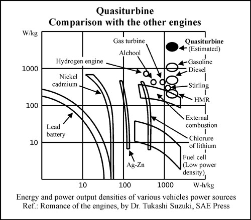
and 12 % of the energy. Furthermore, the best power to weight ratio of the Quasiturbine
(to which the flywheel suppression contributes) gives rise to lighter vehicles (also due
to the suppression of the gearbox) and fuel cost efficiency. The fact that the
Quasiturbine does not require energy consuming peripherals (pumps, came shafts, push rods,
valves...) also constitutes a gain at the level of energy efficiency. (See High-tech
for the detonation mode). Furthermore, the rapid expansion volume just after T.D.C. allows
to extract more energy from the initial hot gas with 3 advantages: thermodynamic
exhaust cool down, less heat transferred to the engine bloc, and less NOx production. Finally, the
exhaust being done symmetrically on both side of the engine, it is not necessary to supply
mechanical work to expel it, better even, the behavior is analog to free space explosion
and create an auto cleaning vacuum in the exhaust chamber. (See also the paragraph on : No
excessive expansion chamber volume increase). Note that the Quasiturbine
mathematical modelisation is represented by a piston placed into an infinite cylinder,
with all the associated advantages. Energy efficiency is related to all the following :
Thermodynamic (gain from early and late mechanical energy extraction)
Thermal (smaller heat flux and cooler operation)
Friction (the product friction X displacement is lower that for the piston)
Peripheral accessories (gain because of no camshaft, valve, push rods ...)
Peak power (only 20% higher that the mean power, compare to 7 times for piston)
Shaft RPM harmonics (which are very low - no need of flywheel to average)
Gear box saving (8 à 12 % energy saving by not using gearbox)
Long live time (wear is measured in number of passages, low RPM means long live)
Intake efficiency (piston has poor sine wave intake characteristics)
On board application saving (lighter vehicles ... means saving over 10 years!)
Fuel additives (Quasiturbine requires much lower octane level)
Environment (fuel savings and much less NOx production)
Vibration zero (source of billions of $ of damages and corrosion acceleration)
Cumbersome (4 time less than the piston engine)
Weight reduction (5 time less than the piston)
Note on the Pressure-Volume diagram: The engines present cyclic
characteristics which are particularly well established by a close curve on a
pressure-volume diagram. In the case of the piston where the pushing surface is strictly
equal to the surface generating the volume, la surface enclosed in the close
pressure-volume diagram curve is then proportional to the work (energy) done by the
gas.
However, this is not generally the case for the rotary engine, and specially for the
Wankel, since the early pushing surface is not of the same size as the surface generating the
volume. The Quasiturbine is however the exception in the world of rotary engine, since its
pushing surface is the same as the volume generating surface, and consequently, the
surface in the pressure-volume characteristic curve is proportional to the energy produces
by the Quasiturbine (those curves will be published later). So, be careful about engine
comparison base on pressure-volume diagram.

Quasiturbine - Model AC with carriages
Quasiturbine - Model AC with carriages
11 - Environment: It is well known that the 2 cycle engines are light and nervous, but also very polluting. The reason for this pollution is due to the fact that, in the 2 cycle engine, the exhaust gas are blown out of the engine by the incoming intake mixture, and in order to have a maximum power, part of this intake mixture passes directly to the exhaust manifold without having been burnt. In the Quasiturbine engine, intake mixtures never come into contact and neither are "pushing" the exhaust gases. Consequently, the Quasiturbine has power characteristics of the 2 cycles engine, while meeting the excellent exhaust combustion of the 4 cycles engine. For environmental reasons, we will most likely stop using actual versions of the 2 cycles soon after the year 2000 (fuel injection being a possible improvement); The Quasiturbine engine will then be one of the few alternatives to consider ! At equivalent power, the Quasiturbine is also much less noisy than the piston engine, since it fractions each expansion into 4 expansions per revolution (or 8 per 2 revolutions for the 4 cycles engine), and expels more progressively on a large angular area. Furthermore, NOx are formed at the end of the durable high temperature and pressure confinement period. Since the Quasiturbine presents a linear volume variation near the T.D.C., the expansion starts earlier than in other engines, which gives less initial pressure and temperature and less time for NOx to form, as well as less heat transferred to the engine bloc. (See High-tech for the detonation mode).
12 - Variety of fuels: In engine mode, the Quasiturbine is an excellent pressured fluid energy converter (pneumatic motors, steam engines, zero leak hydraulic engine for water fall, etc). Large units may be used to produce electricity in coal of heavy oil thermal power plants, or to transform in mechanical energy the residual steams of industrial processes. In addition to the use of conventional liquid petroleum fuels, the Quasiturbine can in principle make use of (if adapted) a wide variety of fuels from methanol to diesel oils, including the kerosene, the natural gas and eventually the hydrogen (See High-tech). About using computerized carbonation, one must realize that the flow in the intake pipe is very continuous, and not shopped like in the piston engine. In fact, the intake pipe load factor is expected to be 3 to 5 times better, so that continuous fuel injection is appropriate without any synchronization (Remember, this is a continuous combustion engine with no valve overlaps or intake backflow. Similarly, the Quasiturbine exhaust pipe is not subject to any tuning). The photo-detonation mode is particularly adapted to multi-fuels, since it does not required carburetor, injector, neither even the sparkplug, but only the pulverization in the intake manifold (at vacuum or at atmospheric pressure). Contrary to the Diesel mode with injector, the photo-detonation mode permits a uniform combustion at lower temperature, and consequently is less polluting.
13 - Electrical integration: The Quasiturbine permits for the first time a complete monolithic integration of the electric generator with a fuel engine (much in demand for hybrid applications, and without vibration). Due to the fact that the center of the Quasiturbine is free, the fixed electrical components can be simultaneously on the central core, and on the peripheral stator. Only the intermediary zone is in rotation. Reciprocally, if the electrical components make a motor, the Quasiturbine becomes an integrated electrical pump-motor, or a bi-energy power plan.
14 - High-tech: Hydrogen is, without a doubt, the highest in high tech fuels. However, high inflammability of hydrogen imposes a stratifiable intake chamber to the engine distinct from that of the combustion chamber (which disqualifies the piston engine) .
The Wankel engine success for direct hydrogen combustion comes for its intake and combustion stratification, which results mainly from early intake (like Quasiturbine) and its excessive volume during expansion (with an efficiency lost). The Quasiturbine engine offers the same hydrogen advantage, without the lost of efficiency and hydrogen oil degradation (oil free). The Quasiturbine meets the fundamental criteria imposed by the "hydrogen" engine of the future (cold intake area, stratified intake, reduced confinement time, low sensitivity to detonation, less pollutant, robust and energy efficiency), and even surpasses the Wankel in this respect, since the intakes are separated by 3 strokes instead of two. On the other hand, contrary to piston engines which have an asymptotic approach to the minimal volume, the Quasiturbine nears and breaks away linearly from this point of maximum compression, which means that the duration of maximum compression ratio is very short, and that if detonation mode is allows, it is naturally triggered at that time, thus permitting total combustion and better performance (characteristic explaining the insensibility of the Quasiturbine to frequent hydrogen detonation). In addition, the high combustion temperature of the hydrogen in presence of nitrogen (air) generates much nitrogen oxide, a pollutant which the Quasiturbine prevent by its short duration pressure pulses. On durability side, it is known that the piston ring break easily in presence of hydrogen, which is due to the fact that the internal ring perimeter is in compression while the exterior rubbing perimeter with the cylinder is in expansion and favors the rapid fragilisation by the hydrogen, a situation unknown in the Quasiturbine. In the case where it would be necessary to reduce the contamination level by micro-particles in the intake, notice that exhaust chamber of the Quasiturbine can be externally ventilated. Also, because it has no oil pan, gravity is not needed to collect oil, and the Quasiturbine can work horizontally, vertically or up-side-down, in a variety of environments (including under water) and in interplanetary space micro gravity. In pump mode, the Quasiturbine does not require a check-valve, thus opening the door to applications in the field of cryogenics.15 - Oil free engine, compressor and pump: In the Wankel engine, the oil pan is also mandatory for shaft, bearings, gears lubrication and thermilization. In the Quasiturbine, oil is not a cooling agent, and is only required at seals friction interface. Use of ceramic or high tech seals can make the Quasiturbine an oil free engine (Thermilization being done by the contact of the carrier wheels). Furthermore, since hydrogen degrade all oil, lubrication free must be developed for hydrogen engine any way. For units built with conventional material, a lubricant can be added to the fuel or the vapor. Notice that units with exhaust in the lateral covers (and not radially) are true centrifuge oil traps, and the needs of lubricant are consequently minimal.
16 - Combustion chamber of superior geometry: The combustion chamber can be positioned at several locations (radially or laterally). We suggest that the chamber be located in a tangential median cut in the rotative blade filler tip such that at top dead center, it is squised between the 2 carriage rollers and the Saint-Hilaire profile on which the sparkplug is located, all such to contain over 80% of the gaseous mixture in a rounded corners cube like shape (at top dead center, the ratio of the visible surfaces to the combustion chamber volume is comparable to the piston. The chamber can be made semi-spherical, cylindrical or else ...). When at bottom dead center, this cut as the advantage to prevent the filler tip to devise the chamber in 2 parts, and insure complete chamber ventilation in the exhaust. By opposition, the triangular rotary piston of the Wankel contains the crankshaft and it is not possible to deeply dig a compact chamber, making the combustion chamber at top dead center of the Wankel long et thin, and the relative contour wall and piston monuments dragging the mixture into an unwanted rolling movement, turning down the combustion at the chamber ends. The thickness of the Quasiturbine combustion chamber permit to completely avoid this mixture rolling drag (a stabilization top wall on the filler tips has been found useless). The carriage rollers have a small contour cut in the median plane of the combustion chamber, such that a continuous gaseous mixture links from one contour seal to the next. It may be interesting to recall that close to the top dead center, the carriage rollers on each side of the filler tip do not reach that filler tip simultaneously (the forward carriage roller reaches first, and then the back carriage roller. Pass the top dead center, the forward carriage quit first, and then the back carriage). Seen from the interior of the combustion chamber, the compression comes from all directions, and it is as well the same for the expansion during the combustion, which can almost be modelised by a 3 dimensional expansion from a compact core ! Notice also that the Quasiturbine geometry permit a very large exhaust opening (particularly radialement) on an extended angular sector (which reduces the work needed to exhaust), and this without exhaust-intake overlapping. As in any engine, for every fuel considered, the combustion chamber must simultaneously have the minimal compression ratio and the minimal volume required (for gasoline, one must have simultaneously a combustion chamber of 5cc excluding the interstices, and a compression ratio of 8), conditions which are easier to realize with large units. Lets add for comparison that the combustion in the Quasiturbine last 1/4 of the shaft rotation, while it last 1/2 for the pistons (2 or 4 strokes), notice the factor 2 (... and not 4 !). For this reason associated to the speed of combustion, it is no surprise that the maximal theoretical rotational speed of the Quasiturbine is only half of the piston one. As a consequence, if the piston engine timing advance is for example of 20 degrees, it will be only 10 degrees for the Quasiturbine (the stroke being distributed on only 90 degrees instead of 180. Notice also that the piston requires such an advance because it is escaping in front of the combustion gas, which is not the case with the Quasiturbine). The piston is very sensitive to synchronization, because it does produce a strong torque only at mid-stroke, while the Quasiturbine is not timing insensible, since its torque profile is flat. The Quasiturbine is particularly well suitable to run in supersonic photo-detonation mode. Some piston engine experts tend to question the relatively complex shape of the Quasiturbine compression chamber (they question in fact and mostly the thermal exchange which may result with the walls), but it appears that at minimum volume, the piston chamber look like a flat disk which is also far from an ideal condition. If the piston chamber characteristics are so critical, it is mostly because of the long pressure impulse generated by the piston. The Quasiturbine produces a much shorter pressure impulsion which make it much less sensitive to the shape of the chamber. Furthermore, in the Quasiturbine, only a fraction of the gas is in the menu contours at the time of fire. The intake and exhaust ports being at different ends of the combustion chamber, it is possible to do a better filling of the chamber by having a simultaneous open overlapping of the two ports, without risking that a portion of the intake gas goes into the exhaust, as it is the case with the piston engine. (See also the paragraph Bigger is better).
17 - Wider power range than conventional turbines: The Quasiturbine operates according to hydrostatic principles, by opposition to conventional turbines which operates along hydrodynamic principles. Just a word here, to recall that the conventional gas turbines are conceived for a precise aerodynamic flow, and do not offer a wide power range with reasonable efficiency. For its part, the Quasiturbine does not use aerodynamic flow characteristic on the blades, and keeps its excellent efficiency on a wide power range. It is the same when the Quasiturbine is propulsed by steam, compressed air, or by fluid flow (Plastic Quasiturbine for hydro-electric centrals, etc). Furthermore, the Quasiturbine does not required superheated steam, neither dry steam, and is particularly suitable for energy recovery, cogeneration, or steam pressure reduction station. The interesting thing about multi-tasking more than one Quasiturbine engines is that they can all share the same common shaft and be individually engaged as power is required by using a simple ratchet coupling, thus giving an increases power range and energy efficiency. (By the way, coupling with a generator, compressor or a pump do not require a Quasiturbine engine shaft, since the coupling mechanism can be fixed on the generator shaft itself, and the Quasiturbine just be slided-in over it).
18 - Possibility of 2 strokes Quasiturbine: Each chamber of the Quasiturbine passes across 4 strokes : intake, compression, expansion, exhaust. In the 2 strokes pistons engine, an external blower is used to insert the combined exhaust and intake strokes at the end of the expansion and the beginning of the compression (those last ones being shortened). In principle, the same can be done with the Quasiturbine, which would gives two simultaneous combustions in the top and the bottom chambers (those chambers can be interconnected by a pressure equalizer tube), canceling out the net load of the rotating blades on the carriers. As it is for the pistons engines, this would permit to almost double the power, against a deterioration of the efficiency and the percentage of burned gas (pollution). The two strokes Quasiturbine would be to our knowledge by far the highest power density engine in weight and volume.
19 - High power density: In order to achieve high power density (in volume and weight), the concept and design of engine must make sure that all components are continuously essential at all time. For example, the pistons of a car engine being independent, each piston is useful while propulsing (17% of the time), but present a rest and an unfortunate drag for most of the time (83%). In the Quasiturbine, all components are continuously essential at all stage of operation, and none experience any dead time. Associated to the continuous combustion, the Quasiturbine is one of the best candidates in the race for high power density engine. This exceptional characteristic has a counterpart: as the material never rest, it must be of the best quality.
20 - Consideration on friction: Fortunately, the modern material permit to reduce considerably the friction, which still is the no. 1 enemy of engine designers. The seal's friction on plane surface of the Quasiturbine can be reduced by using the well known conventional solutions. The blade's rotary joints pose a somewhat different problem, but simple nitrogen treatment seams generally appropriate. Finally, the carrier seat on the rotary blade joint can be more critical. In the case where similar pressure are used in the two independent circuits of the Quasiturbine (case of compressors, steam and pneumatic engines, pumps, QT 2 strokes combustion engine), the opposed pressurized chambers tend to cancel the net load of the rotative blades on the carriers (at least in the square configuration), and no particular measure is then required at the carrier-blade interface. It is different for the 4 strokes combustion QT engine mode, since only one chamber is pressurized and the load is then totally transferred on the carriers of the opposite side. In the case of considerable load (diesel), it may eventually be necessary to use a roller bearing at the carrier-blade interface, and for the wheel's axis. In all even, the product "Friction X Displacement" is lower in the Quasiturbine compare to the piston engine.
21 - Bigger is better: The Quasiturbine in hydraulic, pneumatic or pump mode is little sensitive to the size, and do not present a critical threshold (except for large viscosity). It is different with fuel combustion mode because then, one must simultaneously manage the high pressure, the intake vacuum, and the combustion conditions. One must generally consider two intrinsic factors : the leak ratio = (total length of the seals / volume) which decreases as the square of the size, and the contact ratio = (surface of the chamber / volume) which decreases as the inverse of the size and the confinement time. As those 2 negative factors decreases with the engine size, it is then relatively easier to make running the large unit ! (This is generally also true for other engine concepts). On the other hand, for every fuel considered, the combustion chamber must simultaneously have the minimal compression ratio and the minimal volume required, conditions which are easier to realize with large units.
22 - Self dynamic torque regulation: While rotating, the mass of the piston must be accelerated and decelerated by the crankshaft mainly in the first and last quarter from TDC to TBC, at angular position where the torque generated is low, which amplified the rotational harmonic on the crankshaft. By opposition, the Quasiturbine rotational speed slows down when extending in lozenge and accelerates when retracting into the square shape, which means that the rotor tend to accelerate most near the dead square position where the torque generated is minimum, which self dynamically reduces the engine RPM fluctuations.
23 - Ideal motor for hybrid vehicles: The WHEEL
MOTOR is an element of the hybrid vehicle traction group, as is the necessary
"onboard generator" which recharges the batteries. We think that the
QUASITURBINE is the ideal motor for this indispensable "onboard generator" in
hybrid vehicles, since it meets all the required qualities :
- Zero vibration (the small engine are generally too shaky !)
- Compact (5 times less cumbersome that a piston engine)
- Lighter (5 times less heavy than an equivalent piston engine)
- Less noisy (without muffler : 20 times less than an equivalent piston engine)
- More efficient and less pollutant (500 times less NOx ?)
- And much more ...
24 - Other applications: The data and most preceding comments have been verified, when possible, on the demonstration prototype. These characteristics benefit to all Quasiturbine applications, which include pressured fluid energy converters (pneumatic, steam...), combustion engines, compressor modes, pumps mode, and others.
The Quasiturbine is universal in relation to
energy sources :
Liquid and gaseous fuel, hydrogen, steam, pneumatic, hydraulic...
| Return to main menu |
Quasiturbine Agence, Promotional
Agent for the Quasiturbine Continuous Combustion Rotary Engine or Compressor
Casier 2804, 3535 Ave Papineau, Montréal Québec H2K 4J9 CANADA (514) 527-8484 Fax (514)
527-9530
www.quasiturbine.com
info@quasiturbine.com