Why is the Quasiturbine
not a Wankel type engine ?
The similarities between the Quasiturbine Rotary and the Wankel are
like the ones between the planet Earth and March,
the closer we look, the fewer
there are!
2025 Comparative
Analysis
of Quasiturbine and Wanlel
Rotaty Engine: Two Concepts 100 Years Apart.
https://www.ijsr.net/archive/v14i2/SR25210033851.pdf
WANKEL
 QUASITURBINE
In most crankshaft machines, the moving piston closes the gap with the piston head (TDC - Top Dead Center) at the most distant point from the engine center, while in the Wankel (also a crankshaft engine), the moving triangular piston surface closes the gap (TDC) at the housing area nearest of the engine center! This means that not only the triangular piston surface moves further inward during the stroke, but at the same time the housing wall moves outward as the relaxation progresses! An illogic working behavior, which is not however necessarily a drawback in itself if the difference in swept volume produces pure rotary forces and if the engine can extract it? This shows one of the Wankel paradoxal behavior, and invites everyone to be most careful in understanding engine concepts... Vaguely attributing combustion deficiency of the Wankel to its elongated combustion chamber shape (or its higher surface-to-volume ratio) is a guest or a fast way out, not well done science...
The Wankel engine is based on the principle of volume variation between a curve and a moving cord (a sliding single piston-object on the curve). The Quasiturbine does not use this principle, since the maximum volume as well as the compressed volume are both in a straight line contour area. Today's Wankel engines well master the technology; the deficiency is due to the poor energy efficiency of the principle, not with the technology itself. The Quasiturbine permits 4 improvements: it reduces the relative length of the rotor side (also responsible for high HC unburnt), suppresses all dead times, suppresses the progressive torque evolution and suppresses the need of synchronization gears, which allow for an equal size engine to double the power with an optimum efficiency, and little HC unburnt
| The Quasiturbine inventors have admiration for the work
of Felix Wankel and his successors. The following commentaries are not intended to discredit his accomplishment, but only to establish the factual difference with the Quasiturbine technology. |
Due to its geometry at top dead center, the combustion chamber of the
Wankel is thin
and extends on a wide angular sector (un-optimized 2 dimensional combustion),
while the Quasiturbine has the
advantage of being able to gather an important proportion of the gas
into a near half-spherical cavity at the end of the filler tip of the blades
(favourable 3 dimensional combustion).
|
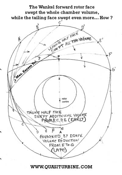
Let looks intuitively at the fundamental Wankel deficiency of excess swept volume (positive at intake, negative at relaxation), by making an analogy to the piston. Consider just one of the Walkel rotor surface, horizontal when at TDC (top dead center) and vertical when at BTC (bottom dead center). By analogy to a piston, the distance (radius) from the engine center to this rotor surface when horizontally (TDC) and then when vertically (BTC) corresponds to the crankshaft drop (stroke) of the "piston surface equivalent", in relation to the engine center.
In a piston engine, the "cylinder head" is fix and does not move during the piston stroke, so that the residual minimum chamber volume at TDC (this exclude the chamber cut inside the rotor surface) is part of the relaxation volume during the complete stroke, and do not vary. Now, observe the residual minimum volume in the Wankel at TDC (which can not be reduced due to the Wankel concept geometry), and notice its variation during the strokes as the apex seal move into this minimum volume area. Contrary to piston, the minimum TDC residual volume is not all present in the chamber during the stroke, which spoil the applicability of the Pressure-Volume diagram and its efficiency criteria.
By analogy to piston, it acts as if the piston head would move down (taking energy) during relaxation, preventing the complete relaxation sweep volume to occur, with a corresponding reduction of efficiency... The opposite volume variation occurs at intake, according to a moving up cylinder head analogy during compression, which prevent full expected sweep volume compression to occur. To illustrate how the Wankel excess volume (positive at intake, negative at relaxation) can affect the combustion relaxation efficiency, lets remember that the pressure pulse is in geometric relation to the volume pulse (faster if considering temperature effect). The first 50% chamber volume variation doubles the atmospheric absolute pressure to 30 psia, while the next 25% volume variation brings it to 60 psia; the next 12.5% to 120 psia; the next 6% to 240 psia ( = 15 bar). This means that a 6% excess volume could result in a 100 psi pressure difference near TDC !
Because the Wankel residual chamber volume at TDC (this exclude the chamber cut inside the rotor surface) can not be reduced due to the Wankel concept geometry, its efficiency deficiency can not be fixed. On the contrary, if you look at the Quasiturbine residual chamber volume at TDC, you will notice it can be reduced to zero, which allows the Quasiturbine to meet the Pressure-Volume diagram efficiency criteria, just as well as the piston can, and this is a prerequisite for any better engine concept...
- The Wankel engine uses a rigid three face rotor with a crankshaft.
- The Quasiturbine uses a deformable four face rotor without a crankshaft.
- The Wankel engine shaft turns at three times its rotor RPM.
- The Quasiturbine rotor and main shaft turns at the same speed.
- The Wankel engine fires only once per shaft (not rotor) revolution (which means three times per rotor revolution).
- The Quasiturbine fires four times per main shaft revolution, producing an
exceptional torque continuity.
The Wankel compression and combustion stroke each last 120 degree of rotor (not shaft) rotation, of which only 90 degrees is effective (no chamber volume variation in the first 30 degrees of compression and in the last 30 degrees of combustion). Exhaust and intake strokes share together 120 degree of rotation in an excessive overlapping (they are partial strokes!).
All Quasiturbine strokes are of equal 90 degrees rotor rotation (not necessarily duration), with useful volume variation (like piston) at all angles and without undesired overlapping.The Wankel fires 3 times per rotor (not shaft) revolution for a total of 12 strokes, but because its power strokes are not jointed and overlapped (three 30 degrees dead times), they are penalized 90 / 360 and count for an effective total of 9 strokes per rotor revolution (even less when considering the effect of excessive exhaust-intake overlap).
The Quasiturbine fires 4 times with a 4 faces rotor, for a total of 16 jointed and completed strokes per rotor revolution.In the Wankel, 2/3 of the work is produced by piston like radial crankshaft force, while 1/3 of the work is done by pure rotational (tangential) force, which the crankshaft is not optimized to harvest (and for which a synchronization casing gear is needed).
In the Quasiturbine, 100% of the work comes from tangential forces and movement, which the tangential differential harvests correctly. - The Wankel residual geometric Vmin of the Wankel is substantial
and 3/4 of this residual geometric Vmin is swept during the stroke.
- In the Quasiturbine, the Vmin is zero,
a zero Vmin volume is swept without effect during the stroke. - When the Wankel engine rotor goes from one T.D.C. to the next,
the torque increases to a maximum value and starts decreasing right away (progressive). - The torque generated by the Quasiturbine gets rapidly to a plateau, and holds this maximum for a long arc before decreasing, producing a better overall mechanical energy conversion rate.
- The Wankel engine has a dead time. A complete rotor (not shaft) revolution is composed of three expansion strokes of 90 degrees, each separated by a 30 degree engine dead time.
- The Quasiturbine strokes are consecutive, with no dead time.
- After some wear of the synchronization gears, the Wankel contour seals do two things: sealing the chambers, and providing some rotor orientation forces. For this reason the seals must have a more absolute positioning which limit the engine lifetime.
- The Quasiturbine rotor orientation forces come from the four carriages (AC with carriages) or from the cylindrical pads (SC without carriage), but never from the contour seals themselves. In the Quasiturbine, the seals' roles are only dedicated to sealing the chambers, and they are differential in positioning, which increases the engine lifetime.
- The center of mass of the Wankel triangular piston is moving in circle with the crank, and this whole triangular mass bangs the seals against the housing, requiring the protection of a housing synchronization gear.
- The Quasiturbine has no crankshaft, and its rotor center of mass is immobile at center during rotation. Never the Quasiturbine seals need to oppose and constraint the whole rotor mass, the only force required being the one to transform a square into lozenge and back to square. This is orders of magnitude less stress on seals than the Wankel rotary piston without its synchronization gear...
- The Wankel engine can not be continuous combustion. While a full expansion stroke occurs (rotor revolution of 90 degrees), intake mixture compression is only partially initiated and not yet ready to be lighted (an additional 30 degrees rotor rotation is required as a dead time).
- Quasiturbine mixture is completely compressed and ready to fire at the end
of each expansion stroke.
- Due to its one single firing per shaft revolution, and the dead time, the Wankel engine needs a flywheel.
- The Quasiturbine needs no flywheel, and consequently has faster acceleration.
- The Wankel's triangular rotor is an internal engine part.
- The Quasiturbine four "pivoting blades" have only one side internal since the shaft sides are in contact with the external environment, and the area is available for external blades cooling.
- The Wankel engine rotor movement must be synchronized by a gear set to follow the stator profile.
- The Quasiturbine does not require any such a synchronization, and consequently is much easier to build (Allowing even for strong plastic (ABS) units for low temperature applications!).
- The triangular rotary piston of the Wankel contains the crankshaft and it is not possible to deeply dig a compact chamber, making the combustion chamber at top dead center of the Wankel long and thin, and the relative contour wall and piston movements dragging the mixture into an unwanted rolling movement in a referential moving with the chamber, turning down (squelching) the combustion at the chamber extremes.
- The Quasiturbine chamber is located in a tangential median cut in the rotary blade filler tip such that at top dead center, it is squeezed between the 2 carriage rollers and the Saint-Hilaire profile on which the sparkplug is located, all such to contain over 80% of the gaseous mixture in a rounded corners cube like shape.
- The Wankel needs 2 sparkplugs because of the gas rolling effect and the thin flat combustion chamber shape.
- The Quasiturbine deep semi-circular or semi-spherical combustion chamber suppresses the combustion gas rolling effect, and consequently, no squelching occurs behind the chamber, and one sparkplug is sufficient.
- The Wankel engine must make use of 3 seals at the triangle peaks (Apex), which meets the engine wall with a variable angle on both sides of the perpendicular (-60 degrees to +60 degrees).
- Since the Quasiturbine seals are seated on rocking carriers, they are perfectly perpendicular to the engine wall at all time, preventing the critical leakproof problem.
- The Wankel engine radial seals are at equidistant and at fix distances.
- The Quasiturbine seals are at variable angular and linear distances, giving relative geometric enhancement to intake, compression, and gas expansion.
- The Wankel engine is a "rotating piston engine" that is subject to a constant circular vibration.
- The Quasiturbine has a fixed center of gravity during rotation, and is a true zero vibration engine (like the turbines), since any weight movement is exactly compensated by symmetric mirror movement through the center. (Be careful not to confuse with unidirectional counter-torque impulses).
- The center of the Wankel engine is part of the oil pan, and contains the mandatory mainshaft.
- In the Quasiturbine, the central main shaft is optional. The center of the Quasiturbine can be empty, and available for electrical components, fan blades, or other devices.
- The Wankel engine has limited port access on lateral covers, due to the presence of the oil pan.
- The Quasiturbine is much more accessible, which allows sealed ports for high pressure compressor, and efficient continuous combustion transfer between chambers.
- In the Wankel engine, the oil pan is also mandatory for shaft, bearings, gears lubrication and thermilization.
- In the Quasiturbine, oil is not a thermal cooling agent, and consequently oil is only required at seal friction interface. The use of ceramic or high-tech seals can make the Quasiturbine an oil free engine (Thermalization being done by the contact of the carrier wheels).
- The Wankel engine crankshaft is taking a considerable sideways pressure load.
- Since there is no pressure load imposed on the absent crankshaft of the Quasiturbine, and since its compressed volume nears and breaks away linearly from its point of maximum compression, Quasiturbine operation in "photo detonation" mode is feasible.
- Since the main Wankel engine shaft rotates at three times its rotor speed, it is more suitable for high RPM end uses.
- The Quasiturbine main shaft (rotating at the same speed as its rotor) is more appropriate for lower revolution end uses (e.g. airplane propeller at only 2000 RPM, generator, transportation, or to reduce gearbox ratio in current applications).
- Since the main Wankel engine shaft rotates at three times its rotor speed, it is not suitable for low RPM compressors or pumps.
- Quasiturbine is suitable for both low RPM compressors and pumps. For the same engine dimensions and shaft RPM, the Quasiturbine presents a substantial 50% power density improvement (and more for power to weight ratio) in its operational range.
- The Wankel has a fast raising pressure pulse compare to the piston engine, but shows a high pressure plateau near the top dead center, due to the slow rotor horizontal translation by the crankshaft at that point.
- The Quasiturbine has a similar fast rising pressure pulse, but no high pressure plateau, which makes it thermally more efficient, and more suitable for photo-detonation, diesel and hydrogen mode.
- Due to its geometry, the Wankel exhaust port is overlapped extensively, opening much before the expansion stroke is over, and closing much after the intake stroke has begun.
- The Quasiturbine does not impose such a wide overlap detriment to efficiency.
- The Wankel engine success for direct hydrogen combustion comes from its intake and combustion stratification, which results mainly from early intake and excessive volume during expansion (with an efficiency lost).
- The Quasiturbine engine offers the same hydrogen advantage, without the loss of efficiency. Furthermore, the Quasiturbine's rotor offers one extra insulation chamber (4 instead of 3) to hydrogen intake.
- The Wankel engine stator profile is an optimum, which can be generated by simple geometric envelope.
- The Quasiturbine "SAINT-HILAIRE stator confinement profile" cannot be generated by geometric envelop technique, and eccentricity can still be accentuated for additional performance.
Textually, the elements of differences could be gathered as follows:
1) The Wankel is a rigid rotor with 3 faces mounted on a crankshaft,while the Quasiturbine has an articulated 4 faces rotor without crankshaft.
The joints of contours of the Wankel form variable angles
from + to - 60 degrees with the perimeter in the course of rotation.
The joints of Quasiturbine are almost always normal with the perimeter contour.
2) The engines of Felix Wankel did not initially include gears
of synchronization with the stator, which gears was introduced only in the 50',
that is to say more than 30 years after the beginning of work of M. Felix!
With wear however, the energy of repositioning at every moment of the rotor
from the Wankel comes more and more from the exerted pressures
by the joints themselves on the perimeter.
Then in Wankels, not only the joints must ensure the sealing,
but they must also direct the rotor (what is responsible to the fact that the Wankel ages badly).
In teh Quasiturbine, the joints do not have an other function but to ensure sealing.
3) the Wankel divides the perimeter of containment into 3 parts
relatively long, and pressure on this great surface
generate a considerable force on the crankshaft which tires.
Quasiturbine divides the perimeter into four parts,
creating a less lengthened favourable chamber,
and pressures towards the center which are less.
4) As a stroke progresses from horizontal to the vertical,
the Wankel rotor needs an additional rotation of 30 degrees
(to make 120 degrees) and to reposition itself at the TDC,
and this idle period of 30 degrees occurs 3 times per turn of the rotor.
The Quasiturbine does not have idle period, since it carries out
the four strokes with its four faces of the rotor,
and when a relaxation is over, the other starts immediately.
Quasiturbine has also other single characteristics,
of which a new management of strokes times
which devotes less time to compression and the exhaust,
and more time and of volume to the intake and the relaxation...
In conclusion, the deficiencies of the Wankel do not come
of its mechanical defects which have been surmounted,
but from a theoretical reason much more fundamental.
Obviously, nobody wants to involve himself in an adventure
which would present the same vexations as the Wankel.
Fortunately theoretical simulations on computer
nowadays allow analysis which the Wankel had never had before.
Quasiturbine is thus not a Wankel engine...
First Approximation
Quasiturbine calculated comparison with the
Mazda RX7 Wankel engine
See detail calculations method at
QT50 Characteristics
The RX7 has a 2 units Wankel engine, with a:
max.
diam. = 9.45"
min. diam.=
7.28", and a
thickness = 3.15" each
Total intake volume of
1,308 litre per shaft rotation
(corresponding to 90 +30 degrees of rotor
rotation)
About 135 HP at 6000 shaft RPM.
Ignoring extra
efficiency of the Quasiturbine, a stack of two Quasiturbines units having similar dimensions would
give a total intake volume of 1.81 litters / revolution, and would develop a calculated 100 H.P. at 3000 RPM
(6000
RPM is likely to be out of the Quasiturbine operational range). Value not actually measured yet. Lets
recall that the main Wankel engine shaft rotates at 3 times its rotor speed,
while the shaft of the Quasiturbine rotates at the same speed as its rotor (and
will probably never reach the maximum rotational speed of the Wankel shaft ?).
For the same dimensions and shaft RPM, the Quasiturbine presents a substantial power density improvement (and more in term of power to weight ratio). But still more important, is the fact that much higher pressure ratio (up to diesel) can be obtained while keeping all engine parameters unchanged (Compression ratio difficult to reach without sacrificing intake volume). Furthermore, unlike the Quasiturbine which is a true zero vibration engine, the Wankel must preferably be assembled by pair with the rotors 180 degrees out of phase in order to partially cancel out the important vibration generated by each unit.
| Return to main menu |
Quasiturbine Agence Inc.,
Promotional Agent for the Quasiturbine Continuous Combustion Rotary Engine or
Compressor
Casier 2804, 3535 Ave Papineau, Montréal Québec H2K 4J9 CANADA
(514) 527-8484 Fax (514) 527-9530
http://quasiturbine.promci.qc.ca/
quasiturbine@promci.qc.ca