During the early 1990's, a theory circulated in California that a 2% reduction
in electricity power consumption would save the cost of a $-multi-billion,
700-megawatt power station. Since that point in time, new more
energy-efficient electric products have entered the market. The list includes
new compact fluorescent light bulbs, the advent of white light LED's, sulphur-fusion
light bulbs, convection ovens, liquid-crystal display TV and computer screens.
Despite the introduction of such technology to market, electrical power demand
is expected to grow by 2% per year in industrialized countries.
Natural Gas Transportation
In anticipation of this expected increase in power demand, new exploration for
natural gas has been underway in Canada's Arctic. New pipelines are planned to
move large volumes of natural gas to Canadian and American markets.
Clean-burning natural gas is the preferred fuel for thermal power stations. It
is collected from a multiplicity of wells using pipes as small as 3-inches in
diameter, then transported over long distances through pipelines that measure
between 16-inches to 48-inches in diameter. Interstate pipes that branch off
from the main pipeline measure 24-inches to 36-inches diameter, while lateral
pipes would measure 6-inches to 16-inches. Local delivery pipes would measure
0.5-inches to 3-inches diameter, with pressure as low as 3-psi.
Compressor stations are located every 100-miles to 245-miles along main and
interstate pipelines, where natural gas pressure may be pumped to between
200-psi and 1500-psi using centrifugal compressors. These compressors may be
driven by gas turbine engines, by piston engines or by electric motors to move
the gas at a typical speed of 20 miles / hour. Control valves to regulate line
pressure may be installed at intervals between 5 to 20-miles along main
pipelines. Such valves would be installed where main pipes connect to
interstate pipes, where interstate pipes join lateral pipelines and where
lateral pipes connect to local low-pressure pipes. The control valves may be
used to reduce line pressure, gas velocity and/or mass flow-rate in the
pipeline. When gas pressure is reduced by a control valve the gas temperature
drops and heat is transferred to the surroundings through the control valves'
metal structure and sometime through direct cooling.
Typically, the pressure potential energy in a 1000 psi gas pipeline is about
3% of the thermal BTU (21,500-BTU/lb) gas flow content. Gas at 1,000-psi and
32-degrees F or zero-deg C has a density of 3.083-lb/cu.ft. When the gas flows
at 30-ft/sec in a 36-inch diameter pipe, the mass flow rate of 653-lb/sec
carries a combustion heating value of over 14,000,000-BTU's over a 1-hour
period or 19,860,000-Hp. Centrifugal compressors raise pipeline pressure at
pumping stations and can add over 207,000-Hp to the gas flowing inside a major
intercity pipeline, after raising pressure from 200-psi to 1000-psi.
Compressor stations located along collector pipelines systems that feed into
the mainline, can add some 196,000-Hp to the gas flow as a result of raising
gas pressure from 3-psi to 200-psi and using a mass flow-rate of 653-lb/sec.
Theoretically, an estimated 20% of the mainline pumping energy can be
extracted at the main pipeline control valve, where the pressure drops from
1,000-psi to 200 psi as it enters a local pipeline system. This can be
accomplished by replacing the control valve with an engine. Of the over
196,000-Hp that was expended to raise gas pressure in short-distance collector
lines from 3-psi to 200-psi, an estimated theoretical maximum of 85,000-Hp
could be extracted in local lines at customer transfer points. At these
points, pressure-drop engines could be installed to reduce line pressure from
200 psi to 3 psi prior to entering customers' premises. However only very
large purchasers of natural gas would have an interest in installing such
engines on their premises.
During an earlier time, no suitable pressure-reduction energy recovery engines
were available to install at natural gas pipeline transfer points. New
positive-displacement rotary engines have recently been developed that have
little need for lubrication can be installed at pipeline transfer points that
involve a large flow-rate of gas as well as large drop in line pressure. These
engines could provide base-line electrical power for numerous large customers
of natural gas.
The Quasiturbine in the Gas Line
At several locations along the gas pipeline pressure and flow-rate may be
reduced using engines (rotary expanders) instead of control valves. Heat
energy that the control valves release into the atmosphere could become
electric power. The Quasiturbine www.quasiturbine.com is a low-friction,
positive-displacement rotary engine that can be installed where high-pressure
pipelines connect to local low-pressure lines. Because conventional turbines
can not be widely modulated in rpm, they are not suitable for gas flow and
pressure control. The Quasiturbine is essentially a closed valve at zero rpm.
It and has high efficiency and high torque and over a wide rpm.
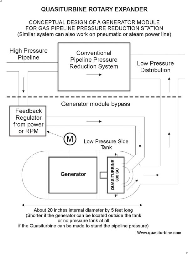
Photo courtesy Quasiturbine.com
High-Pressure (200-psi) Release
Quasiturbine pressure-reduction engines may be installed where a main gas
pipeline (1000-psi) connects to a regional pipeline (200-psi). The engine at
such a location would use a pressure ratio of 4.74, allowing a Quasiturbine to
operate using full (no dominant restriction) inlet ports, which means that
there is no significant gas expansion within the chambers. To reduce the need
for lubrication, patented roller carriages may be installed into the engine.
When operating with natural gas, the engine will have a volume expansion ratio
(V2/V1) of 3.24, meaning an engine cut-off ratio would be set between 20 % to
a maximum of 24 % depending on engine clearance volume.
Before inlet cut-off occurs, an inlet pressure of 1,000-psi will push on to
the rotary cylinders. Gas expansion will occur after inlet cut-off, reducing
pressure to 200-psi. For gas flowing at 30-ft/sec inside a 36-inch diameter
pipe, volume flow rate will be 212-cu.ft/sec. For a pressure
differential of 800-psia, this will give 800-lb/sq-in x 144-sq.in/sq.ft x
212-cu.ft/sec = 24,430,000-lbf-ft/sec or 44,400-Hp. The
rest of the engine expansion will involve gas temperature dropping by a factor
or 1.46 and an estimated isentropic efficiency of 79 %. With gas temperature
at 32-degrees F, its density would calculate to 3.08-lbm/cu.ft (density =
pressure / (gas constant x absolute temperature)).
Power resulting from expansion would calculate to 3.08-lb/cu.ft x
212-cu.ft/sec x 0.5099-BTU/lb-deg-F x ((32-deg F + 460-deg F)-((32-deg F +
460-deg F )/1.46)) x (3600-sec/hr)/2545-Hp-hr/BTU) = 132.7-Hp at
100%-isentropic efficiency. This would raise total engine output to 44,532-Hp
or 33,176-Kw . Overall expansion engine power may be increased if the gas were
heated prior to pressure reduction and an intercooler cooled engine exhaust
gas. If engine inlet temperature were raised to 540-deg F (1000-deg R),
expansion engine power would be raised to 269.79-Hp and overall engine power
would be raised to 44,670-Hp or 33,279-Kw. The added complexity would result
in raising power output by less than 1 %, however, it would serve to keep gas
pipeline pressure above the freezing point of water. Ignoring gas
expansion and considering only the gas pressure flow, a 36 inches diam. gas
pipeline at 700 psi carry typically a pressure power in excess of 30 MW - 25
millions of pound-ft/sec - of zero pollution pure mechanical energy.
Low-Pressure (3-psi) Release
The low-pressure release system would be used where gauge pressure in the
local lines may read as low as 3-psi and burners receive this gas at
atmospheric back- pressure. This means that the absolute pressure in the local
line system would be 17.7 psia. Local lines would typically be located several
miles downstream of a compressor station, where the gas pressure would be near
to 215-psia and temperature near the freezing point of water. Pressure
reduction from the main pipeline can be cascaded into 2 or more steps into the
local service line. The Quasiturbine could operate using inlet- ports dominant
restriction to make sure some expansion actually occurs within the chamber.
The following table can give an idea of relevant data to the gas transfer
point:
|
Phigh* P2/P1 T2/T1 V2/V1 Cut-off Th TL Isen 214.7 12.13 1.83 6.61 15.10% 540-F 85.3-F 89% 314.7 17.78 2.01 8.83 11.32% 600-F 66.7-F 90% 414.7 23.44 2.15 10.89 9.18% 640-F 51.2-F 91% *Phigh denotes absolute gas pressure upstream of the engine (Psia); P2/P1 denotes pressure ratio based on downstream pressure of 17.7-psia; T2/T1 denotes engine upstream/downstream temperature ratio; V2/V1 denotes engine volume expansion ratio after inlet valve cut-off; Th is the upstream gas temperature (degrees F) when heated prior to expansion; TL is the engine exhaust temperature at 100% engine isentropic efficiency; Cut-off is the percent expansion volume when the inlet port closes; Isen is the estimated engine isentropic efficiency at the port cut-off ratio. |
Engine performance is calculated based on natural gas having a gas constant of R = 96.33 ft-lbf/lbm-deg R, a specific heat Cp = 0.5099 Btu/lb-deg R, a specific heat ratio of 1.321 and a lower heating value of 21,500-Btu/lb. The following table gives data on engine performance based on a gas mass flow-rate of 1-lb per second and a counter-flow heat exchanger effectiveness of 75%:
|
Phigh Thigh Tex Isen Tex' Power Heat in Gas used 214.7 540-F 85.28-F 89% 135-F 292-Hp 488.5-Hp 0.017-lb/sec 314.7 600-F 66.72-F 90% 120-F 245-Hp 546.2-Hp 0.019-lb/sec 414.7 640-F 51.15-F 91% 104-F 273-Hp 584.7-Hp 0.020-lb/sec |
The term Tex' is the engine outlet temperature after the isentropic efficiency
of the engine has been taken into account. Gas used is the amount of natural
gas that will be burned to heat the natural gas (from the freezing point of
water) that is to be expanded in the gasline pressure / flow-rate control
engine. The engine power is calculated from the temperature difference across
the engine (Th - Tex) x Cp x 3600-seconds-per-hr/2545-Btu-Hp-hr (Eg; (540 -
135) x 0.5099 x (3600/2545) = 292 Hp).
A High Efficiency Application
When 1-lb/sec of natural gas is combusted in a turbine engine operating at 35
% efficiency, 30,412 Hp in thermal energy would be released and converted to
10,644 Hp on the power turbine drive-shaft. The pressure control engine
processing 1-lb/sec natural gas would yield between 2.7 % to 3 % of the power
of a gas turbine that burns 1-lb/sec natural gas. On extensive natural gas
fired power grids, Quasiturbine pipeline energy-recovery engines could provide
low-level power to small markets at remote locations along the gas pipeline at
competitive cost. The heat absorbed along the pipelines by the control valves
reducing line pressure, would otherwise be dissipated.
Inter-Cooling and Reheat
The "thermal efficiency" of the Quasiturbine pipeline pressure control engine
would be high because it would use no energy compressing the gas. That work
has been done at the pipeline compressor station, the operating cost of which
would be recovered from the sale of natural gas to customers. Thermodynamic
efficiency could be improved by raising engine inlet temperature; however, the
temperature that enters the local gas distribution network would need to be
kept low. If the engine exhaust temperature is too high for local
distribution, the exhaust can be cooled in an inter-cooling heat exchanger.
Combustion will occur in the main heat exchanger.
The high-pressure natural gas coming from the main pipeline will receive
primary heat in the intercooler then be superheated in the main heat exchanger
before being expanded in the engine. Before entering the local distribution
network, the low-pressure engine exhaust gas will release its heat to the cold
incoming gas in the intercooler. Engine efficiency can be improved and power
output could be raised by 45% using higher engine inlet temperature and the
intercooler. The use of the intercooler and a re-heater will allow for cascade
(high-pressure, reheat, low-pressure) operation of 2-Quasiturbines.
The table below shows data with regard to engine performance using inter-cool:
|
Phigh P2/P1 T2/T1 Th TL TL’ Tex Power Heat in Gas used 214.7 12.12 1.83 1000-F 336-F 409-F 126-F 426-Hp 659-Hp 0.0218-lb/sec 314.7 17.77 2.01 1000-F 265-F 338-F 109-F 476-Hp 710-Hp 0.0234-lb/sec 414.7 23.43 2.15 1000-F 218-F 288-F 96-F 513-Hp 746-Hp 0.0246-lb/sec |
The use of the intercooler increases the pressure-reduction engine’s output at a flow-rate of 1-lb/sec to between 4% and 5% of the power output of a gas turbine burning natural gas at a rate of 1-lb/sec. Smaller pressure-reduction engines that flow under 0.1-lb/sec of natural gas could be used at industrial buildings.
Natural-gas fired industrial
boilers as well as building heating systems usually operate with a
heat-transfer effectiveness of 85%. If the boiler or heating system supplied
1,500,000-BTU's per hour (589.39-Hp) of heat, 82-lb/hr of gas would be
burned. To reduce outside pipe pressure from 200-psi to 3-psi inside the
building, an inter-cooled Quasiturbine could be installed into the supply
line. It would produce 82/3600 x 426 = 9.7-Hp or 7.2-Kw of power to an
alternator and supply at least 6.5-Kw of useable electric power to
maintain basic level building operations during winter months.
If regulators and natural gas companies were willing to allow externally
heated Quasiturbine engines to be used to reduce line pressures at gas
pipeline system transfer points, a substantial amount of low-cost electric
power could be generated for local use. As an example, a survey (M. Dehli, GWF
Gas-Erdgas 137/4, p.196, 1996) showed that in Germany alone, the potential for
utilizing this pressure was 200-700 MW in 1996, and the gas consumption has
increased since then... This is the equivalent of tens of mega windmills on
kW-h basis!
Strategic Local Electrical Backup
At a time where electrical networks suffer some instability an their
reliability are questioned following spectacular black-out, this could be of
great interest as a stable strategic local power source, not only for the Gas
Pipeline companies themselves, but also for priority local needs like
hospitals and public services.