|
Quasiturbine Heat Pump
From an Hot Air
Engine Reversible
« Quasiturbine Stirling and Short Steam Circuit »
Stirling Quasiturbine
Made Heat Pump
Forcing the Quasiturbine shaft to turn reverses the thermal process and
the Quasiturbine becomes a Heat Pump!
Driving this device with an external motor
will also move heat from one quadrant to the next.
The hot compressed gas will give its heat to a quadrant,
while the following gas expansion will take heat (cold) from the next one.
In reverse cycle, this device is a complete loop and an integrated "Quasiturbine Heat Pump" with heat exchangers.
(Such a compact device is not possible with piston, because both compression and expansion occur at the same physical
location,
which is not the case with the Quasiturbine)
Furthermore, no polluting gas or liquid is required.
The air or liquid-cooled component can be as needed hot or cold.
Quasiturbine Heat Pump Advantage
In the Quasiturbine Stirling, all the engine shell is pressurized with
helium,
so that the inter-chambers leaks are automatically recycled by the central
region, and required only sealing of a turning shaft (comparatively to the sealing of the back and forth piston connecting
rods,
unless sealed machines, which the Quasiturbine also can be).
No regenerator.
Since the gas is moved sequentially rather that alternately from the zones
of different temperatures,
the Quasiturbine Stirling is exempted from the need of a regenerator
without efficiency lost, which increases its power output through an increase in RPM.
The Quasiturbine has no need either for a "gas displacer".
More torque. Instantaneous resulting torque on the rotor is more
constant than in internal combustion mode (but less powerful) because it
has 2 positive contributions by revolution about 90 to 120 degrees in
duration each, that is one push and one pull. For each revolution of the
Quasiturbine rotor, each one of the four pivoting blades receives a push
at the top and at the bottom hot plate (approximate angular location), and
a pull at the left and the right cold plate, that is 8 pushes and 8 pulls,
for a total of 16 torque impulses per rotation, which levels out the
instantaneous torque fluctuations, increases the power density, and removes
the need for a flywheel (further reducing substantially the engine weight
and size).
Faster rotation. Because each Quasiturbine pivoting blade goes through
2 pushes per revolution compare to 1 for the piston, the same time
constant would means that the Quasiturbine rotor RPM would be half of the
piston equivalent machine. However, time constants in the Quasiturbine are
anticipated to be quite shorter, so that about the same RPM can fairly be
expected. Consequently, based on equal chamber volume, a Quasiturbine
rotor will produce up to 16 times more power than a piston (8 times due to
the geometrical frequency, and 2 times due to the RPM), and hopefully with
less than 16 times the heat flow...
More power per pound.
The Stirling Piston engines are known to be large and heavy,
which the Quasiturbine-Stirling concept should solve, because there is no
pipe or external accessory or heat exchanger required.
Conventional Piston Stirling engines need inter-chamber connecting pipes to carry
the gas to and from the cold and hot areas (displacer side spacing plays
the same role). Those pipes are passive extension of the compression
chambers, and since they are kept at a near constant intermediary
temperature, their gas content does not actively participate to the pushing
effort, but rather attenuates them. The Quasiturbine Stirling concept
suppresses the need for such interconnecting pipes, and allows for higher
peak pressure in the chambers, and consequently higher specific power
density. Quasiturbine offers up to 16 times more power than a piston
with a comparable chamber volume! The
Quasiturbine-Stirling is further vibration free.
Mechanical Conversion of Low Heat
From looking at the USA energy flow chart at
https://flowcharts.llnl.gov/
The amount of Low temperature heat discarded is quite
impressive. This waste energy has a tremendous potential for energy recovery,
and the Quasiturbine offers more ways to tackle the challenge through Brayton,
Ranking and Stirling cycles!
Principle
Compressing a gas makes heat, while expanding it makes cool. Contrary to piston
where heat and cooling occurs at the same physical location, in a Quasiturbine
the heat and cooling occurs at different angular sectors of the QT engine block,
which provide an interesting heat pump characteristic. In principle, driving the
QT Stirling with an external motor would make it a most compact heat pump without much hardware.
The principle is very simple. A fix amount of gas (work
better with helium) is kept in the chambers of a positive displacement machine.
This gas is heated just after TDC and cooled just after BDC. The speed and the
level at which the gas can be heated and cooled is the limitation of this
concept, which is generally limited to low power and low rpm, and has poor power
to weight ratio. However because it has no intake and no exhaust, not only the
piston gets a push from high pressure, but it gets a pull from the cold gas,
which is in part responsible for the higher efficiency.
You have a thermodynamic cycle (Brayton or Rankin), with
proper selection of temperature and pressure, you are likely to be able to run
this cycle within a Quasiturbine without any boiler, reservoir, pipe, or pump!
General advantages are efficiency and low noise, and
ability to turn on any external motor. A reversible Stirling will always be Stirling, and the Quasiturbine objective is not to compete with other types of
Stirling, but with current heat pump design with its own environmental benefits in
specific applications.
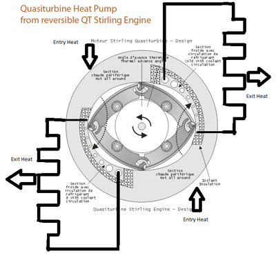
Quasiturbine Heat pump
Consider a Quasiturbine
without any intake or exhaust port,
where all the chambers are filled with the same quantity of a compressible
gas,
and suppose that two opposed quadrants are kept at high temperature,
while the two others opposed quadrants are kept cooled. The rotor surface
could be thermally insulated.
Since there is a lag time in the gas temperature variation,
it is in fact desirable to apply the heat with some advance on their
respective quadrants. Like for the piston, the Quasiturbine Stirling is not self-starting, and has a preferential
direction of rotation.
Initiating the rotation will move the
cool gas into the hot area
where it will expand and produce a torque,
until it get cooled again in the following quadrants and so
on.
This rotation is provided by two simultaneous opposed closed gas circuits,
each one working on the Stirling thermal engine principle
(mechanical work produced by a
close fluid circuit simply from a constant heat flow between two hot and
cold poles,
by opposition to hot-air-engines which are hot-monopole devices, since they generally intake fresh air at ambient temperature and exhaust
their hot residual gas).
The 4 poles
Quasiturbine Stirling cylindrical concept

The figure is showing arbitrary angular lengths
and positions of the hot
and cold zones.
An alternate flat geometric arrangement would
be to use one lateral enlarged flat side engine cover as a cold plate linked to the corresponding cold radial zone,
and the other lateral enlarged flat side engine cover as a hot plate
linked to the corresponding hot radial zone.
This would give a sandwich like compact disk engine with wide flat head
exchanger surfaces
particularly appropriate for solar free space applications (with cold
shadow side). Please visit the page:
«
QT Stirling
and Short Steam Circuit Engine»
www.quasiturbine.com/ETypeStirling.htm
From a Reversible « Quasiturbine Heat Pump »
More Technical
Stirling-Hydraulic
Quasiturbine Locomotive
http://www.geocities.com/harryc11
Combined heat cycle with Quasiturbine Stirling engine
|
