|
Since this website is widely
dedicated to education,
and because early projects are precious part of the innovation history,
the QT50AC first project is more than a curiosity...
Q50AC Basic Drawings
Understanding...
While most rotary engines use the principle of volume
variation between a curve and a moving cord, this new engine concept makes use
of a "seven degrees of freedom X, Y, q, ø1,
ø2, ø3, ø4" rotor, trapped inside an internal housing contour, and does not
require a central shaft or support. This concept is the result of research for
an hybrid turbine-piston engine with a fixed center of gravity during rotation
(zero vibration). The invention is an assembly of four carriages supporting the
pivots of a four-element, variable-shape rotor. This rotor rolls on the inner
surface of a profiled stator shaped like a skating rink (just like a roller
bearing). During the rotation, the rotor components align alternatively in a
lozenge and a square configuration. This device can act as a pump, a compressor,
a flow meter, or as an engine (including pressurized fluid mechanical energy
converter). It is self-synchronized and uses no valves (only fixed ports in the
stator or alternatively, ports on the lateral side covers). Central support of
the rotor is not required for most applications. Four cycles are completed in
every rotation. The maximum geometrical compression ratio is a function of the
maximum diagonal ratio selected at design. As for turbine engines, ignition is
only required initially, since combustion is kept continuous between successive
cycles by way of an ignition transfer slot or cavity. The continuous combustion
produces an enhanced dynamic compression ratio. The device incorporates few
parts. It has an excellent torque continuity even at low rpm (Due to its high
torque pulsation rate, this device requires less flywheel effect and gearbox
ratio for most applications). It is suitable for uses such as aeronautics, where
high reliability is required. Having no oil pan, it can be operated in
completely submerged or hostile environments. The asymmetry of the strokes and
the precocity of the mixture intake and gas expansion (without excess volume
during expansion) allow for a better initial mechanical energy conversion. A
fast reduction in the combustion chamber of the temperature, the pressure and
the confinement time leads to less NOx production, and less heat
transfer toward the engine block, all contributing to improve the power density
and the efficiency over the piston engine. The Quasiturbine meets the hydrogen
engine criteria.
Drawings and photos
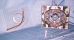
Quasiturbine Engine - Stator profile, with groove
and quasi circular
pressure ring positioning.
QT50 Data
BASIC DATA EXAMPLE:
Major axis = 5.570". Minor axis = 4.700"
Each chamber volume = 1.49 po2 x
thickness (po)
Displacement volume per rotation = 4 x 1.49 x
thickness (po) , po3/rotation; or 4 x 9.6 x thickness (cm) , cm3/rotation
Assuming a thickness of 2.000"
Aspirated volume per rotation = 11.9 po3
/rotation; or 200 cm3 /rotation
(The power generated must be compared to a 2 stroke
engine)
"Saint-Hilaire" contour
Comment on the
"Saint-Hilaire" contour profile calculation

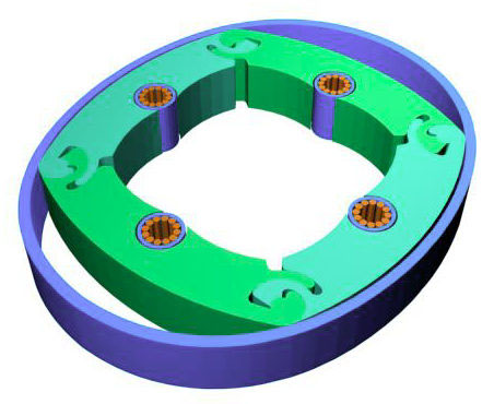
Quasiturbine Engine - Components template
(Lozenge,
carriage & mechanical coupling)
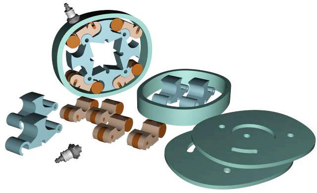
Blow up diagram of the
prototype
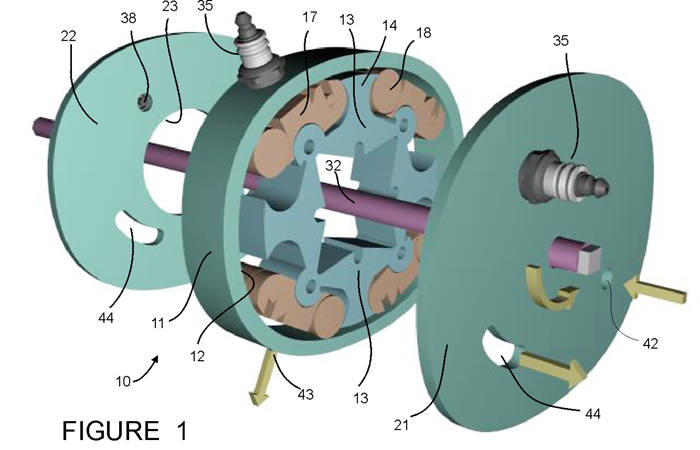
Click on the illustration for a higher resolution

Quasiturbine Engine: Blow up of stator, rotor assembly,
carriages, port positioning and mechanical coupling.
(Square arrangement on the left, lozenge on the right)
10 - L'ensemble moteur
11 - Boitier incluant 2 parois
12 - Contour SAINT-HILAIRE
13 - Pale pivotante
14 - Bourure
15 - Prise de traction
16 - Pivots
17 - Chariot
18 - Rouleau
19 - Centres de rouleau
20 - Trajectoire centre de Pivots
21 - Paroi avant
22 - Paroi arrière
23 - Ouverture dans paroi arrière
24 - Joint tiroir
25 - Join papillon
26 - Joint divisé avancé
27 - Ressort plat |
28 - Joint linéaire
29 - Joint arc
30 - Joint circulaire
31 - Joint chariot
32 - Arbre
33 - Bras de couplage
34 - Tringles de poussée
35 - Bougie
36 - Canal d'allumage
37 - Fenêtre de bougie
38 - Fenêtre de bougie paroi
39 - Fenêtre
40 - Bouchon
41 - Fénêtre carburateur
42 - Fenêtre carburateur paroi
43 - Fenêtre échappement
44 - Fenêtre échappement paroi |
More Photos
(click on the photo to enlarge full page or view more photos)
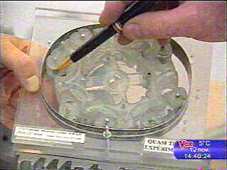
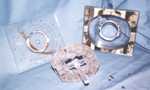 Plexiglas prototype: Rotor assembled, with the
stator and lateral covers. Plexiglas prototype: Rotor assembled, with the
stator and lateral covers.
 Plexiglas prototype all assembled in the stator,
with the lateral covers. Plexiglas prototype all assembled in the stator,
with the lateral covers.
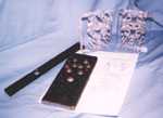 Perforation template applied to Plexiglas
prototype. Perforation template applied to Plexiglas
prototype.
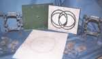 Drawing template for stator profile, with lateral
covers. Drawing template for stator profile, with lateral
covers.
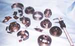 Some anterior prototypes ! Some anterior prototypes !
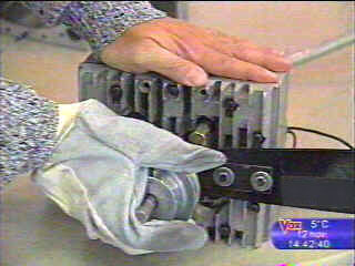
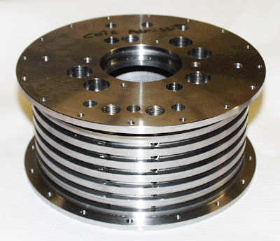
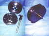 The first metal prototype built in February 1997 The first metal prototype built in February 1997
More Technical...
QT50AC
Characteristics
|
