|
|
This page is de continuation of the Academic Pneumatic Partial Kit page at:
quasiturbine.promci.qc.ca/EProductQT75SCAcademic.htm
Quasiturbine QT.6LSC
(previously QT75SC)
Pneumatic
Academic Partial Kit Assembly
Guide
It is the buyer and/or operator
responsibility
to comply
with all applicable national
and local laws and rules,
including those on security and pressurized products.
This document is written to be used by an intermediary machinist or
mechanist.
If you do not understand some sections, you are invited to consult a
professional. The Quasiturbine technology is quite recent and very few people
are familiar with it. Do not make the assumption that you know or that what you
think it makes sense. Rather, follow attentively the instructions
and read again at each later dismantlement and
re-assembly.
Technical Warnings
I - The rotor is a deformable assembly articulated
in square and lozenge.
OUT OF THE STATOR, NEVER FORCE
THE DEFORMATION
OF THE ROTOR PASS ITS LIMIT, nor knock on the pivoting blades to articulate the rotor
(what could distort the pivots and the contours seal grooves).
II - Never use abrasive grinding paste, NOT EVEN IN "VERY SMALL QUANTITY"
(hardly visible quantity).
NEVER ADD GRINDING PASTE TO THE ASSEMBLED ENGINE.
III - If the rotor does not turn freely
by
hand,
DO NOT PRESSURIZE IT, NOR INSIST.
DISMOUNT IMMEDIATELY
to find and correct the defect,
otherwise irrevocable damages can occur on the interior face of the stator or
elsewhere.
IV -
WARN INGESTION OF FOREIGN BODIES IN THE QUASITURBINE.
A way is to use screen and make sure the intake
line goes from bottom up.
V - These units must be supplemented,
assembled and be operated under the constant supervision of a competent adult.
It is recommended not to exceed 500 RPM and/or 2 bars (30 psi) at the
pressure gauge (less than 1 HP flow in).
About Parts Provided
The partial kit includes:
-
A set of 4 pivoting blades slightly oversized in thickness.
-
A steel stator housing slightly oversized in thickness, whose interior surface is
already rectified and polished,
and including 4 radial ports (two intakes and two exits,
standard NPT 1/2").
-
A set of 4 slightly oversized contour seals and their associated springs
(seals which have to be slightly rectified to accommodate the contour).
-
4 roller cylindrical supports and 4 axes for the pivoting blades.
-
A suggested internet drawing to help making the lateral side covers
(see the assembly guide).
-
A simplified differential and a central
shaft diam. 3/4 inch.
-
The present Internet Assembly Guide giving
indicative instructions for assembly.
VI - The rotor and the stator
thickness must fit. These parts are delivered slightly over-dimensioned.
Do not use electric tools or motorized grinding stones.
It is recommended to make this dimension setting by hand
with the
already encased pivoting blades ones in the others (Always match the
pivot sequence marks - Facing the one or two dots)
by using sandpaper posed on a plane surface, the rotor being then caped also
by a plane
object. The rotor must have good parallelism in its two extreme lozenge
positions. It is recommended to deform it while lapping.
Control the rotor thickness for different geometries deformation by squeezing it in-between
two flat surfaces.
Attention not to deburer (to round the edge) in the stator interior, which
would increase the leaks.
For the compressed air, it is suggested a minimal difference in
thickness of 0,002" (maximum 0,005")
between the rotor and the stator, and check free rotation once assembled
(the stator has no preferential direction of rotation, but the rotor pivot
interstices must be ahead of the chamber when rotating).
Multiple tests will guide you towards the optimum value.
Multiple resumptions of the dimension settings of the stator
and rotor are generally possible.

QT.6LSC (previously QT75SC) Pneumatic
(the simplified differential and its shaft actually replace the
central cross).
(Rotor average diam. 6 inches, by 2 inches in thickness)
VII - The interior surface of the stator was already brought to the dimension and reasonably polished.
It is necessary to avoid deteriorating this critical surface, because it would
be so to speak non repairable...
This surface requires a complex polishing equipment - Do not attempt to regrind
this surface.
VIII - Fitting of
the grooves and the contour
seal. Each pivoting blade comprises a contour
seal
which must move freely in its
groove. It is suggested not to sandpaper
or grind the
interior of this grooves, but rather to notch it using a blade of
appropriate dimension -
typically 3,18 mm (0,125") - with square and sharp
ends.
The back and forth of the end of this blade should be enough to fit the
grooves.
The set of parts includes slightly
oversize seals,
the length must be brought back to about 0,004"
shorter than the thickness of the stator, otherwise the lateral side covers will
be damaged (Important, smooth all the cutting edge at the ends of the contour
seal).
Once at the right dimension, the contour seal sleeve (when present)
must be slightly squeezed with its contour seal inside to insure the best
movement with minimum
friction.
The edge of the seal in contact with the stator
housing contour must be round on a stone to avoid gripping,
and the opposite edge must be grinded down in order to leave a reasonable
play once the rotor is assembled.
Undulated springs to place behind the contours
seals are provided and their tips must grip into the seal notch, not to scratch the
lateral side covers.
Always check the free and unrestricted movement of these
seals during the
rotation. Each blade jointure has a transverse seal across in the shape of a «V»
of which the tip must be directed toward the center of the engine. The embossed
harm of the «V» must be in the bottom of the grove, while the straight harm must
slip on the cylindrical part of the jointure.
IX - Supporting blade rollers axis and the simplified differential. These parts
are provided and already assembled in the pivoting blades and the rotor at
delivery. If needed, it is possible to dismount them and put them back up again.
They do not require any intervention other than checking the length to ensure a
sufficient gap in between lateral side covers. Lubricate well all the parts.
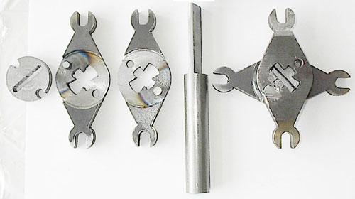
Simplified differential (design may vary) :
The components on the left, the shaft at the center,
and a view once the left parts are assembled on the right.
This is for low to moderate torque only, the coupling being non-reversible
(The shaft can not be used to drive the rotor -
Hand torque shaft will give a wrong apparent high rotor friction).
Advantage: The shaft can be removed from the motor
(and inserted in the opposite direction).
About Parts NOT Provided
X - Central
supporting rollers and bearings of the
pivoting blades. These parts are not provided,
because they must be made according to
the residual tolerances measured
between the rollers on the rotor
and the supporting track in the lateral side covers. It is strongly suggested
to mount these rollers on bearing (e.g. Torrington B56),
and their external diameter will be close to 0,780"
(thickness of 0,370") in order to allow a free movement of the
lateral side cover tracks in and out of
the rotor.
Polish the sides of the rollers with their bearing and make an initial generous
lubrication
to avoid wear against lateral sides covers and the rollers shaft
support.
Important : The roller set must hold firmly the rotor, and this is why it is
always somewhat difficult to enter the last side cover tracks into the rotor
(If force is needed, undersize the
external diameter
0,002" a shot of the rollers supporting the pivoting blades). The central 1/2" diam.
roller hole of the blade
must be exactly reamed and the bearing casing (type Torrington #B56)
lock (punching the contour hole) to prevent axial bearing movement in its hole. Do not attempt to rotate the rotor without the 8 wheel-bearing
well in place on the supporting tracks.
These rollers wheel-bearing are as important as the bearings in the pistons engine,
and an attempt to rotate without them shorten the engine life time to a few
minutes !
XI - The lateral side covers are not
provided because they can take several external forms
(square, rectangular, circular. ..) to suit the local needs. They do not present however any particular
difficulty of making.
Although the commercial versions require a quality steel, the
demonstration versions are well
served with ordinary steel. Aluminum is not suitable unless a flat steel sleeve is added and a steal ring
insert is used for rollers tracks.
The lateral side covers can be cut in the mass in
one part (suggested), or be made of two
pieces welded together.
The following suggestive drawing present a possible distribution of the positioning of
the housing bolts. Notice the protuberant track.
It is important to
precisely position the holes of the housing bolts,
because
their location are also used for centering the stator.
The central circle on the lateral side cover drawing is
the maximum diam.
suggested for that opening.
A smaller diameter hole would improve the cover rigidity
(as for example a 1" diam. only to accept a needle bearing type Torington
#B128).
One of the lateral covers may have 10-24 threaded stator holes
to conveniently
avoid using nuts !
Important - Do not pressurized the central area
- Never plug the lateral side cover ventilation drain.
Because this pressure will add up to the centrifugal force
and risk to fracture the rotor.
For the QT75, at least 2 ventilation drains of 1/4 inch diameter
must be drilled in the central area on one or the other of the lateral side
covers.
XII - Stator housing bolts. These bolts are not
provided.
It is suggested to use 3/16" (10-24)
bolts of sufficient length and quality.
The cheap steel bolts elongate with time and are not adequate. Use only forged
steel bolts grade 9 or higher (Allen head). The in-line air accumulator (minimum
1 litre) nearby the engine intakes to attenuates the intake line perturbations
are not provided neither.
Suggested assembly procedure
Do not hammer the pulley (gears or coupler) on the shaft
(this could break the safety pin).
Use a puller to extract, and a large C-clamp to insert.
XIII - It is recommended not to set apart the rotor blades. If
this must be done, great care should be taken:
- To mark the 4 blades sequence to make sure they are reassembled in the same
order, matching the male-female pivot.
- The transversal pivot seal is a fragile component in a <V> shape. The Tip of
the <V> should point toward the engine center, and the flat side should slip on
the moving blade. Do not hammer the seal in, but push it in delicately without
interruption, while guiding to avoid flexion.
- The friction pad higher curvature end should be the one extending outside the
pivot.
Assemble and test one step at a time.
Place the rotor without its contour seals and none of its rollers in the engine casing
and tight all the bolts
(important to avoid the deformation of the lateral side covers). Ensure that the rotor moves freely.
Put it apart, add the contour seals and bolt it again to check the free rotor
movement in between the two lateral side covers.
Keep doing that way for each assembly step.
This way of doing is crucial not to damage the components of the engine.
A resumption of the thickness of the rotor and stator are generally
possible,
but the 4 axes, 4 supports and 8 rollers of
central pivoting blades
should not exceed the total thickness of the
stator. Check the lateral side covers with a ruler for deformation.
Excessive torque on the contour bolts or the insufficient lateral side covers
rigidity may lead to spherical cap deformations,
and make impossible the proximity leakproof rotor condition with the lateral
side covers.
XIV - The centering of the stator side covers on the set of supporting central
rotors is tight and self done. However, the stator housing profile has no
centering marks, except in reference to the housing bolts.
Before closing the cover, it is recommended to extend the rotor fully in the
diamond configuration (or where the global play is minimum with the the stator),
and to make sure all four contour seals are equally extended.
Angularly, make sure that the stator is in the
wanted position in relation to the
lateral side covers orientation.
Ensure that the bolts are
straight and perpendicular, or better, substitute some temporarily by rigid
rods at time of assembly.
Use external appropriate spacers at top and bottom,
and on the left and the right, in order to hold the stator correctly.
Check the 2 side covers for concentricity before tighten the
bolts (which covers maybe deformed and spoil the later verification) by
squaring the side covers one an other at different positions on the perimeter.
To avoid lateral side covers deformation, place 4 cylindrical spacers, diam. 1/4" and having the same length as
the stator thickness (0.004 inch more), near the engine attachment holes on the external
perimeter. Control the
external planitude. Tight the bolts progressively in alternate opposite and well,
because they must immobilize the stator in place.
Turn the rotor slowly by hand, and if there is a hard spot, positioned
the rotor on it, unbolt and re-bolt. Repeat until the resistance to rotation is
constant around (this is most important before any attempt to pressurized the
Quasiturbine).
The small aperture stator ports are intended for intake, while the
large aperture ports are for exhaust,
determining the direction of rotation, which must be the same as the preferential
direction of rotation of the rotor. In between two successive contour seals,
localize the jointure interstice, which should be behind of the chamber when
the rotor rotates.
XV - Use of anti-grip past : This paste is
not essential, neither recommended,
but it can facilitate the start-up by decreasing the risk
of damaging the parts,
particularly on the pivoting blades, the
grooves and contour seals,
like on the interior surface of the stator when use for the
first time.
Others suggestions
XVI - Use an hand key tool to position at will the rotor by hand.
For checking the assembly
and before each start up by compressed air, it may be
useful to turn the rotor by hand.
For that, it is recommended to use a hand key
tool fitting on the shaft.
Before concluding that the engine is difficult to turn, it is recommended to
move the hand key tool alternatively in both directions and from both side of
the engine. The central simplified differential has a slot
to insert the flat part of the shaft of 3/4" diam. (thickness 3/16").
For a better holding and self centering, a different shaft could have its flat
section extended
such as to enter also in the opposed side cover bearing, and even further
extend outside the engine where it could be lock-in. The simplified
differential efficiently smooth out the engine torque. Be careful to always remove the hand key before
running the engine !
XVII - A foot base for
engine support is necessary. The engine
can produce violent kickback,
and as it has a substantial weight, it is imperative to immobilize it well
before each use.
It is thus essential to built a solid and adequate holding support.
Take care of the engine attachment method in all circumstances:
Important : Always attach the engine by only one of the lateral side covers
(the one on the power takeoff side)
using short bolts in peripheral holes,
in order not to add undesirable pressure in-between the 2 side covers, which
could deform the engine casing.
XVIII - Lubricate periodically with Air Tools Oil (nothing else)
and only by the intake air line (Never use oil with additive like
antifriction, because large air flow or steam oxidized the oil and
precipitate the additives in glue like product fatal to the Quasiturbine
operation). During the
first 2 braking-in running hours,
periodically add oil in the feeding air line to help exiting the braking-in
particles.
Later, use moderate oil quantity and no more oil than necessary to wet the chamber
walls.
Furthermore, since the rotor lateral leakproof is only assumed by
the lateral side covers proximity,
a generous periodic lubrication help to complete the leakproof.
This engine is not
particularly demanding on lubrication,
but the materials chosen for these units require nevertheless a periodic
lubrication.
Every hour of operation, add
some pneumatic tool oil drops in the
intake manifold
(motor oil emulsions, oxides and crystallizes under adiabatic cooling, so it
is not recommended).
Do not allow excessive oil or liquid accumulation in the central engine
area
to avoid blade fatigue
by hydraulic lock of the micro pivots cavities.
Periodically, dip the flat section of the shaft in oil (use air tools
oil only)
to lubricate the central power grip zone.
XIX - The operating temperature. Air
expansion produces a powerful cooling.
These units
are intended for demonstrations of short durations
of 30 minutes or less. If the
unit must go for uninterrupted longer periods,
monitor the temperature of the
lateral side covers and stop at once
if it
does increase even slightly over the intake air temperature.
This unit has no dilatation provision for use with steam - Do not run
it hot.
XX - The static or dynamic
rotor balancing has not been verified
and is generally not required for demonstration.
Everyone is free to improve the balancing at will if desired.
Condition of Operation
-
It is the buyer and/or operator
responsibility
to comply with all applicable national and local laws and rules,
including those on security and pressurized products.
-
Familiarize yourself well beforehand with the Quasiturbine
technology (see the associated site at:
quasiturbine.promci.qc.ca).
-
For optimum performance, the feed line must be well
balanced between the two intake ports, which must be done by ending the line
passed the 2 T by an accumulator (buffer) tank (minimum 3 litres), on which
the pressure gage can be located.
-
Always make it turn gradually (without abrupt acceleration).
-
In break-in phase, reposition the rotor away of a dead spot before each
start,
by turning the central shaft.
-
Always ensure that the rotor is adequately lubricated (pneumatic tool oil
only). (Never use oil with additive like antifriction,
because large air flow or steam oxidized the oil and precipitate the
additives in glue like product fatal to the Quasiturbine operation).
-
Ensure that the hoses and fasteners (particularly the flexible) are of
quality and well anchored.
-
Avoid intake flow restriction like low flow rate
regulator or additional flexible air hose. Place a pressure gauge close to
the engine intake or on the end of the line damper tank. Pressure at the
gauge can be fixed by varying the hand ball valve opening.
-
It is recommended not to exceed 500 RPM and/or 2 bars (30 psi) at the
pressure gauge (less than 1 HP flow-in). No free running at more than 20 psi,
and for short period only.
-
Avoid flow restriction at exit.
-
The use of a tachometer (with magnetic pick up, like the one used on bicycle
?) is cheap and also recommended.
-
Once in use, the engine will progressively break-in and rotate better and
better,
periodical dismantlement may require little break-in period every time...
- Never exceed the recommended limits.
- Important - Do not pressurized the central area -
Never plug the lateral side cover ventilation drain.
Safety Precautions
-
It is the buyer and/or operator
responsibility
to comply with all applicable national and local laws and rules,
including those on security and pressurized products.
-
These units must be supplemented, assembled and
operated under the constant supervision of qualified adults.
-
Anchor the unit well on a table before each start-up.
-
Never exceed the limits and suggested conditions of operation.
-
Wearing safety glasses, mask and fastened hair is recommended.
Use ear plugs when noisy.
-
The demonstration room must be well ventilated.
-
Check the tightening of the bolts and adapters. Be wary of the rupture
or the decoupling of any of the flexible hoses.
-
Have a distant valve at hand to cut the air flow (nitrogen) as
needed. Never operate while alone.
-
Particularly during breaking-in under compressed air, it can happen that
the rotor stops at a dead point,
and refuses to turn when the pressure is applied. This situation is unstable and call for urgent pressure release.
In absence of pressure, slightly turn the rotor with the central
shaft and pressurize
it again...
-
During the demonstration, nothing should approach the central zone of the rotor;
make observations at a distance of 50 cm (20 po.) or more.
-
Always be careful, never run it alone et always keep a prompt
hand on the intake pressure valve. Follow closely the instructions.
Remark on Pneumatic Efficiency
An high efficiency pneumatic motor does not guaranty the high efficiency of
the entire pneumatic system. All gas heat up during compression and cool down
during relaxation. The cooling effect must not be under-estimated. As an example,
a typical 200 bar (atm.) cylinder empty adiabatically (without thermalization to
ambient temperature) gives at the end an air so cold that its volume is then a
1/4 of that of the air once back to the ambient temperature (isothermal
relaxation). In those temperature conditions at the entrance of a pneumatic
motor, the efficiency is catastrophically low and the lubricant solidified,
increasing considerably the internal engine friction... Generally, the
reversibility of the compression - relaxation cycle reduces with an increase in
pressure, which favors for high efficiency consideration the use of the lowest
design pressure possible. The measurement of the exhaust temperature gives
generally a good indication of the efficiency, since the minimum of energy lost
into the environment correspond to an exhaust temperature equal (neither
inferior, nor superior) to the ambient temperature. This condition can be
achieve by a slight heating (solar) of the gas before its entry into the
pneumatic motor. Since the Quasiturbine rotates from pressure as low as 1/10 of
atmosphere (bar) (one psi !), one understands why the Quasiturbine is so well
adapted to high efficiency system... For high pressure drop (not allows with the
unit), an air heating coil would be necessary to prevent freezing of the
oil within the Quasiturbine.
QUASITURBINE TRONÇONNEUSES
Manufacturer under a privileged QT-Rotors supply license
agreement
Casier 2804, 3535 Ave Papineau, Montréal Québec H2K 4J9 CANADA
(514) 527-8484 Fax (514) 527-9530
Associated website quasiturbine.promci.qc.ca
info@quasiturbine.com
Subject to changes without notice - December 17, 2004
|
|

